
2B (2.2 Beta)
WARNING THIS IS A BETA RELEASE MANUAL NOT FOR 2.106 FIRMWARE
Welcome
Congratulations on purchasing an E-Stim Systems 2B™. Given sufficient care your 2B™ unit should give you many years of erotic electro-stimulated pleasure. Before starting always read the instructions and ensure you are completely familiar with all of the controls and the safety warnings prior to use.
We have tried to make the control system simple and easy to use, without compromising on the features available. You should find something for everyone, and if you don’t then let us know.
|
SAFETY WARNING (DO NOT CONNECT THE E-Stim Systems 2B UNIT OR ANY ELECTRICAL DEVICE TO ANY LOCATION ABOVE THE WAIST (ACROSS THE ARMS COUNTS AS ABOVE THE WAIST!), BUT ESPECIALLY DO NOT CONNECT ACROSS THE HEART, CHEST, NECK OR HEAD. DO NOT USE IF FITTED WITH A PACEMAKER OR ARE PREGNANT. REMEMBER YOU USE THIS DEVICE AT YOUR OWN RISK. YOU MUST READ AND UNDERSTAND THE USER MANUAL AND ALL OTHER INSTRUCTIONS BEFORE ATTEMPTING OPERATION. |
Index
WARNING THIS IS A BETA RELEASE MANUAL NOT FOR 2.106 FIRMWARE
Congratulations on purchasing an E-Stim Systems Series 2B™. Given sufficient care your 2B™ unit should give you many years of erotic electro-stimulated pleasure. Before starting always read the instructions and ensure you are completely familiar with all of the controls and the safety warnings prior to use.
We have tried to make the control system simple and easy to use, without compromising on the features available. You should find something for everyone, and if you don’t then let us know.
Key Features
|
|
Power and Control
As well as offering all the interesting modes like Pulse, Tickle and Squeeze, the 2B will run in three different power levels. ‘L’ (for LOW power) is the default setting and is ideal for those people who are just starting out on their E-Stim experience, whilst the ‘H’ high power setting takes the 2B unit into a whole new realm of serious power output. The new ‘D’ Dynamic mode allows the output power level to be directly controlled by the Channel levels. Follow the link for more details on the power system.
The 2B can also be operated from the mains via an optional DC/Mains adaptor. This is a high quality switched mode device that is designed to provide the 2B with exactly what it needs in terms of power. We recommend you DO NOT attempt to use other power supplies, as they are not designed for this unit. Doing so may invalidate your guarantee.
|
SAFETY WARNING (DO NOT CONNECT THE E-Stim Systems 2B UNIT OR ANY ELECTRICAL DEVICE TO ANY LOCATION ABOVE THE WAIST (ACROSS THE ARMS COUNTS AS ABOVE THE WAIST!), BUT ESPECIALLY DO NOT CONNECT ACROSS THE HEART, CHEST, NECK OR HEAD. DO NOT USE IF FITTED WITH A PACEMAKER OR ARE PREGNANT. REMEMBER YOU USE THIS DEVICE AT YOUR OWN RISK. YOU MUST READ AND UNDERSTAND THE USER MANUAL AND ALL OTHER INSTRUCTIONS BEFORE ATTEMPTING OPERATION. |
WARNING THIS IS A BETA RELEASE MANUAL NOT FOR 2.106 FIRMWARE
E-Stim Systems is a multi award winning company and we have been creating dedicated Erotic Electro Stimulation systems since 2004.
We don't make anything else and with a wide range of designs, we are considered by many to be the experts when it comes to erotic electro play. We ship around the world, from two webstores (https://www.e-stim.co.uk for UK and the EU, https://www.e-stimsystems.com for the US, Canada, Australia and the rest of the world.) We also have an active user support forum at https://www.e-stim.net and a growing YouTube Channel https://www.youtube.com/estimsystems
Quality for Life
All of our Premium electrodes and Power units are designed and manufactured in the UK and come with a lifetime guarantee.
WARNING THIS IS A BETA RELEASE MANUAL NOT FOR 2.106 FIRMWARE
What is E-Stim
E-Stim is simply using electricity to stimulate parts of the body. Using a dedicated E-Stim unit, rather than a TENS or home build device ensures you can play safely and gives you a much wide range of sensations to enjoy.
What do you need?
In order for E-Stim to work you need, a power unit, an electrode and a cable to connect the two together. The power box generates the signals that create the sensation. The electrode connects that sensation into or onto the body, depending on what the electrode is. Electrodes can be used on the surface of the skin, or inserted into the lower orifices.
E-Stim requires two points of contact. The current and thus the sensation flows between these two points and you then feel the sensation.
Keep Safe - Play below the waist
Generally we say play below the waist until you understand the issues and risks involved with play above the waist. Remember crossing current from hand to hand can run across the chest and is thus something we would not recommend you do.
WARNING THIS IS A BETA RELEASE MANUAL NOT FOR 2.106 FIRMWARE
Step 1
Read this manual and familiarise yourself with the controls.
Step 2
Step 3
Turn the 2B on. (The power slide switch can be found on the bottom of the control unit). The display should light up and the 2B will go through its self test. You should now see a screen like this

Now turn the 2B off. If for some reason you see a different display, then you can perform a Factory Reset to get everything back to the default state.
Step 4
Choose electrodes. The 2B is supplied with a simple set of Sticky pad electrodes and 2mm cables to get you started, but we do offer an ever increasing range of E-Stim Electrodes and accessories. See https://www.e-stim.co.uk and https://www.e-stimsystems.com for more details.
Step 5
Connect things up. Always ensure the 2B is switched off when connecting or disconnecting electrodes.
Step 6 and 7 and 8 .......
Turn the 2B back on
Now you can start experimenting with the modes
WARNING THIS IS A BETA RELEASE MANUAL NOT FOR 2.106 FIRMWARE
The 2B unit has five user controls. Each control allows the user to adjust a particular aspect of the output. It is the operation of the controls in combination that will allow the user to provide an effective electro-stimulation session.
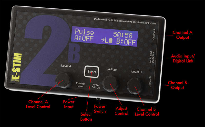
The controls are (from left to right)
Channel A Level Control
The Select Button
The Adjust Control
Channel B Level Control
There is also a power slide switch (on the bottom side of the unit) and an LCD contrast control (accessed from the rear of the unit.)
Channel Level Controls
The channel level controls adjust the absolute level of the output of the relevant channel. Each Channel control value is displayed on the LCD screen, with values from OFF (0) to MAX (100%). OFF is zero output, MAX is full output. The output levels automatically drop to OFF when selecting a mode, and will always start off at OFF (0%) when selecting a new mode.
Select Button
The select button is used in conjunction with the Adjust control, to change and adjust the settings in all the various modes, including changing and selecting the modes themselves. The Select Button responds to a light press, there is no need to press too hard. Pressing and holding the Select Button while rotating the Adjust Control allows further adjustments of the Feel in many modes.
Adjust Control
The adjust control is used in conjunction with the select button, to change and adjust the settings in all the various modes, including changing the modes themselves.
Depending on the mode, the 'C' and 'D' values can be adjusted using the Adjustment Control. Turning the Adjustment Control either clockwise or anticlockwise will change the 'C' adjustment value up or down, while pressing and holding the select button and turning the Adjustment Control which change the value of the 'D' setting. Not all modes use both the C and D values.
Displays
The 2B has 3 display elements, the bright backlight LCD display, giving the user details of all of the functions of the 2B, from control settings to helpful messages.
The two blue LEDs on the right hand side of the unit illuminate in proportion to the intensity of the relevant output. The LEDs might appear to glow slightly when the unit is turned on and there is no output - this is due to the internal reflection of the backlight and is not a fault.
The LCD display depends on the mode but the basics are:-
Top Line
showing the Mode, (the current program mode) and Adjust Values (Dependant on the Mode, the first value is altered by the Adjust Control Knob and the second value by Select + Adjust Control Knob)
Bottom Line
Showing the Level of Channel A, Join Control Status , Current Output Map, Power Mode, Battery Level (if not using Mains Adaptor) and the current Level of Channel B
Power Level Display
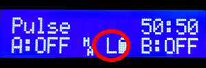
The Power Level Display shows the current power level the 2B is set to. Options are L - Low, H for High and D for Dynamic. For more details on the power level selection system see Power Selection
Battery Level
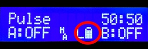
The Battery Level Display shows the current battery level. The more the battery is empty the lower the charge. If the 2B is connected to the mains then the battery will not be displayed
Adjusting Contrast
To change the contrast of the LCD, turn the unit over, and with a small insulated cross head screwdriver insert into the hole in the rear of the unit and gently adjust the cross head adjustment inside. Adjustments should not be necessary as the contrast is set during testing in the workshops.
<picture to follow>
WARNING THIS IS A BETA RELEASE MANUAL NOT FOR 2.106 FIRMWARE
The 2B is powered by a single 9V PP3 alkaline battery. Although it is technically possible to use rechargeable batteries with the 2B we do not recommend them as they almost always have issues with power delivery. If you are seeking more power, then we strongly suggest you consider using the optional mains power supply.
We do NOT recommend the use of Zinc Carbon batteries with your 2B control unit.
- Ensure the unit is switched off, and any electrodes are disconnected.
- Turn the unit over and using a small screwdriver or a fingernail inserted into the battery compartment slot, gently prise the battery compartment cover out.
<Pictures to follow>
Remove the old battery (if fitted) and replace with a fresh Alkaline PP3. The battery connector is polarized so it should not be possible to connect the battery incorrectly, but ensure the polarity is correct before attempting connection.
- Place the battery into the unit and replace the battery compartment cover. The cover is fitted with two tabs which insert into the lower half of the case first, and then the top half of the cover will clip into position.
- Turn the unit over. The unit is now ready for operation.
- Please note we do NOT recommend the use of zinc carbon or rechargeable batteries due to their general poor performance with the later firmware versions..
In the event the 2B unit is not being used for a period of time, remove the battery to avoid any potential damage from battery leakage.
WARNING THIS IS A BETA RELEASE MANUAL NOT FOR 2.106 FIRMWARE
The battery level indicator shows the current level of the battery. There are 4 battery level symbols, indicating Battery FULL, 2/3 full, 1/3 full, and Battery empty. If you have plugged in the optional mains power supply then the battery symbol will not display. As the 2B uses a standard alkaline 9V PP3 battery, a brand new battery should show full*, however the unit will continue to operate with ‘flat’ batteries with a reduced output. This is designed to allow you to make the most out of a battery.
If your 2B starts to reset itself when higher power levels are selected, then this is generally a sign the battery might need replacing.
The battery level display will update whenever a control is adjusted. Due to processor constraints the battery symbol does not display in the Audio Modes.
*Because of the variations in battery manufacturing technology, a brand new battery may not necessarily display a full battery symbol.
Click this link for details on how to change the battery
When the E-Stim Systems mains power supply is plugged in, No battery symbol is displayed.
WARNING THIS IS A BETA RELEASE MANUAL NOT FOR 2.106 FIRMWARE
Its not all about Power
Power seems to be a major target for many people when purchasing an e-stim unit, but without the understanding of how power relates to play it is difficult to ensure you get the most out of any unit. Units that quote a straight power output such as 80mA are generally TENS based units that give no indication how the generated waveform actually provides the sensation of power delivery. Like a racing car, power is not just down to horse power but is related to how it is delivered.
The 2B is considered to be a powerful unit, but if you want even more power, then consider the optional power supply, which will give you around 30% more than battery alone.
Modes for Variety
The 2B has number program modes designed for pleasure and stronger sensations. Don't be surprised if the modes don't give you want you straight away. Nothing ever everything works for everyone, at least on the default settings, so experiment. Because of the way we have designed the wave forms, not every mode will provide you with sensation at the same point, nor will every mode give you the sensation that someone else feels, even with the same settings. E-Stim is a complex subject almost like an art form for many, and it can take practice to find our what you enjoy. Enjoy the journey.
Waveforms created for Sensation
E-Stim interacts with the nervous system of the body in order to provide a sensation. This means that the nature of the waveform is crucial, providing maximum sensation to the nerves, but with a reduced amount of energy that can cause heating and damage to underlying tissues. All E-Stim Systems devices utilise AC based wave forms so there is no issues with DC causing tissue damage, and the waveforms are developed to maximise the sensation as effectively as possible.
Feel
All of our modes have some control over feel. Feel adjusts portions of the waveform to give to a difference in feel, from soft and spiky at one end, to harsh and hard at the other. The choice is down to you.
Power Control
Power delivery depends on the unit itself, the power source (using a 2B with a power supply with give an increased sensation of power), the Levels set, the settings of the adjustments, the current mode, Box level, output map, electrodes used and electrode positioning. All of these elements combine to give you a wide range of sensation from a tickle up to and beyond a hard throbbing pulse.
Power Levels
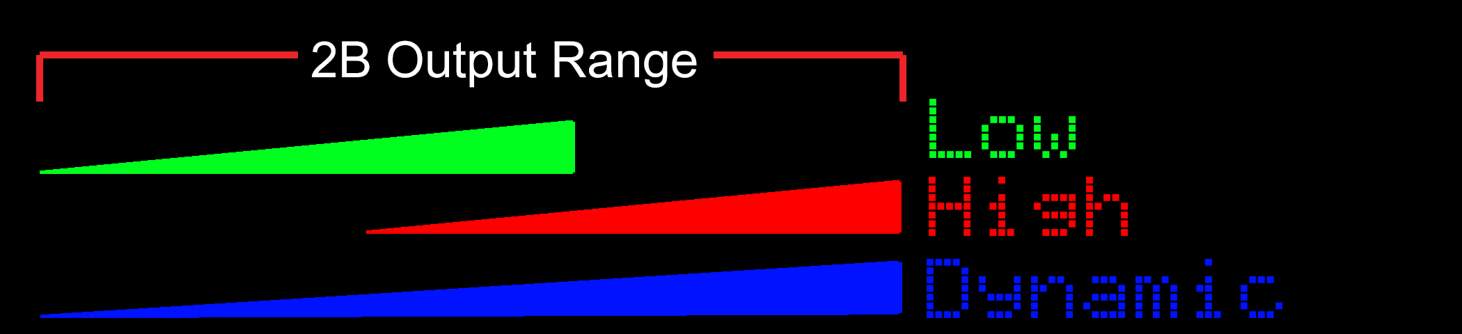
The 2B operates in 3 main power settings, with each level having a 0-100% setting. Low Power, is the default, High Power exists for more experienced players and Dynamic Power gives the benefit of both, but with a lessened control range, with the power output determined by the Channel Settings. For more details on the Power Systems follow the Power Systems Link
Output Maps
As well as the Power Level (Low, High and Dynamic), the 2B has a series of Output Maps. These user selectable maps give even more variety to the output of a 2B. more details on the output map system can be found in the Output Maps section.
WARNING THIS IS A BETA RELEASE MANUAL NOT FOR 2.106 FIRMWARE
Outputs
Connection to any electrode is via two heavy duty 3.5mm mono jack sockets. Ensure the 2B is switched off before inserting or removing the connector to eliminate the possibility of either inadvertent electric shocks or short circuits occurring. When removing the connectors. Grip the insulated shaft of the connector, not the wire and gently pull.
Connections to your E-Stim 2B use industry standard 3.5mm mono jack plugs, compatible with a number of other manufacturers control units and electrodes.
<picture>
Inputs
<picture>
Connection to audio devices and the digital link system is via the centre 3.5mm stereo jack socket. Ensure the 2B is switched off before inserting or removing the connector to eliminate the possibility of short circuits occurring. When removing the connectors. Grip the shaft of the connector, not the wire and gently pull.
Ensure that audio devices or the digital link are only connected to the centre jack socket. Connecting to either of the output jack sockets will destroy your audio unit. The audio input is designed to operate with low level headphone style outputs. It is not possible to operate the Digital Link at the same time as the Audio Input. The Digital link cable despite appearances is NOT a standard USB cable. DO NOT attempt to attach any other USB cable to the 2B digital link input, you will destroy your 2B and invalidate your guarantee.
DO NOT attempt to connect an output to an input. It will destroy your 2B unit, and possibly the item you connect to.
WARNING THIS IS A BETA RELEASE MANUAL NOT FOR 2.106 FIRMWARE
It is possible to use an external power supply with the 2B, but because of the isolation and safety issues when connecting to the mains we strongly recommend you only use an E-Stim Systems supplied universal power supply. The plug socket is beside the on off switch.
Always ensure that when you connect the external power unit, the 2B is switched off.
Insert the plug into the socket, switch the mains power on, then switch the 2B on. The display should light up as if batteries were fitted.
Use of the power supply will offer around a 30% Power increase.
When the power supply is connected, the Display will no longer show a battery symbol, as the 2B is no longer running off Battery.
WARNING THIS IS A BETA RELEASE MANUAL NOT FOR 2.106 FIRMWARE
Fire mode is designed to emulate the Fire mode on the ElectroHelix. It allows you to FIRE or Zap the subject connected to the outputs, for a long as the Select Button is pressed. You can choose the output or outputs. The Output Level is controlled by the standard output level controls.
Fire mode is available from beta firmware 2.131 onwards
Selecting Fire Mode
To select the Fire Mode, press the Select Button once and rotate the Adjust Control to select the mode
[PIC Coming Soon]
Now press the Select Button to choose the currently displayed mode. In this case Fire Mode.

The screen shows the mode (Fire) and the Feel value(50) on the top line, together with the selected output, in this case Ch B - Channel B then, on the bottom line the Channel A Level, Output Map, Output Power Setting, Battery Level and lastly the Channel B Level.
Using Fire
Rotate the Adjust control, to select the active outputs.
Ch A will only trigger the output on Channel A, Ch B will only activate the output on Channel B, Both will activate both outputs at the same time. Feel allows you to adjust the feel value when no output is selected, - by pressing the Select Button and rotating the Adjust control while Feel is displayed). Choosing Exit, and then pressing Select again will allow you to exit the mode.
The chosen output or outputs are only active when a level for that channel has been set greater than 0, AND the Select button is pressed. The output or outputs are only active while the select button is pressed. Release the select button, the outputs will cut off.
Output levels are controlled by the Channel Level controls and would normally need to be set higher that you would normally use on other modes.
Feel Control Adjustment
To adjust the Feel in Fire mode. Rotate the Adjust Control until the displays shows Feel. Press and Hold the Select Button while turning the Adjust Control. The feel value on the screen will then change. The range is from 1-100. You can also adjust the Feel setting while the outputs are active.
Fire mode is not accessible from Commander.
Output Display
If a channel level is set to 1% or more then the corresponding output LEDs will remain on as a warning that the channel may be active at any time.
WARNING THIS IS A BETA RELEASE MANUAL NOT FOR 2.106 FIRMWARE
In Pulse Mode both of the outputs pulse on and off together with equal on and off times. The Adjustment Control allows the user to adjust the pulse rate (how quickly they pulse on and off) and is adjustable from 1 (slow) to 99 (fast). Higher numbers indicate a faster repetition rate. The second value on the display, is the pulse feel, allowing you to adjust the sensation of each individual pulse, from soft to spiky, with values from 1 to 99. The amount of time the pulse is on is equal to the amount of time off.
Selecting Pulse Mode
To select the Pulse Mode, press the Select Button once and rotate the Adjust Control to select the mode

Now press the Select Button to choose the currently displayed mode.
The screen shows the mode on the top line, then the Pulse Speed and Pulse Feel (50:50), on the bottom line the Channel A Level, Output Map, Output Power Setting, Battery Level and Channel B Level.
Changing Values
To change the Pulse rate rotate the Adjust Control. You should see the first number on the top right of the screen change. Lower values indicate slower pulses. To change the Pulse Feel press and hold the Select Button while rotating the Adjust Control and you should see the second value on the top right of the screen change. The Pulse Range is also effected by the use of the TimeWarp function. Output levels are control by the Channel Level controls.
Pulse Range
The Pulse Rate is from around 1 second to 0.02 seconds with Time Warp set to x1, increasing to around 35 seconds to 0.5 seconds with Time Warp set to x32
WARNING THIS IS A BETA RELEASE MANUAL NOT FOR 2.106 FIRMWARE
Bounce mode is so named because the outputs ‘bounce’ from channel to channel. The outputs pulse alternately. The adjustment control allows the user to adjust the pulse rate from 1 to 99. Higher numbers indicate a faster pulse rate. As with the pulse mode the second value on the display, is the pulse feel, this allows you to adjust the sensation of each individual pulse, from soft to spiky, with values from 1 to 99.
Channel A is on when channel B is off and visa versa.
Selecting Bounce Mode
To select the Bounce Mode, press the Select Button once and rotate the Adjust Control to select the Bounce mode.

Now press the Select Button to choose the currently displayed mode.

The screen shows the mode on the top line, then the Bounce Speed and Bounce Pulse Feel (50:50), on the bottom line the Channel A Level, Output Map, Output Power Setting, Battery Level and Channel B Level.
Changing Values
To change the Bounce rate rotate the Adjust Control. You should see the first number on the top right of the screen change. Lower values indicate slower bounces. To change the Bounce Pulse Feel press and hold the Select Button while rotating the Adjust Control and you should see the second value on the top right of the screen change. The Bounce Range is also affected by the use of the TimeWarp function. Output levels are control by the Channel Level controls.
Bounce Range
The Pulse Rate is from around 1 second to 0.02 seconds with Time Warp set to x1, increasing to around 35 seconds to 0.5 seconds with Time Warp set to x32
WARNING THIS IS A BETA RELEASE MANUAL NOT FOR 2.106 FIRMWARE
In Continuous Mode both of the outputs are active. The Adjustment Control allows the user to adjust the sensation of the outputs, from soft to spiky, with values from 1 to 99.
Selecting Continuous Mode
To select the Continuous Mode, press the Select Button once and rotate the Adjust Control until the screen shows 'Continuous'.

Now press the Select Button to choose the currently displayed mode.

The screen now shows the mode on the top line, then the Feel (50). On the bottom line the Channel A Level, Output Map, Output Power Setting, Battery Level and Channel B Level.
Changing Values
To change the continuous feel rotate the Adjust Control. You should see the number on the top right of the screen change. Output levels are controlled by the Channel Level controls.
WARNING THIS IS A BETA RELEASE MANUAL NOT FOR 2.106 FIRMWARE
In Split modes the outputs are split between Pulse and Continuous. In A Split mode Channel A output is continuous, Channel B is pulsed. In B Split mode Channel B is continous and channel A is pulsed. The adjustment control allows the user to adjust the pulse rate from 1 to 99, with low numbers indicating a slow pulse. The second value, is the pulse feel, that allows you to adjust the sensation of each individual, from soft to spiky, with values from 1 to 99.
In Split Mode one channel has a continuous output, the other output pulses on and off together with equal on and off times. The Adjustment Control allows the user to adjust the pulse rate (how quickly they pulse on and off) and is adjustable from 1 to 99. Higher numbers indicate a faster repetition rate. The second value on the display, is the pulse feel, allows you to adjust the sensation of each individual pulse, and well as the feel of the continuous output from soft to spiky, with values from 1 to 99. The amount of time the pulse is on is equal to the amount of time off.
Selecting Split Mode
To select the Split Mode, either A Split or B Split, press the Select Button once and then rotate the Adjust Control to select the chosen mode

Now press the Select Button to choose the currently displayed mode.

The screen shows the mode on the top line, then the Split Pulse Speed and Pulse Feel (50:50), on the bottom line the Channel A Level, Output Map, Output Power Setting, Battery Level and Channel B Level.
Changing Values
To change the Pulse rate of the pulsing channel rotate the Adjust Control. You should see the first number on the top right of the screen change. Lower values indicate slower pulses. To change the Pulse Feel press and hold the select button while rotating the Adjust Control and you should see the second value on the top right of the screen change. The Pulse Range of the pulsing channel is also affected by the use of the TimeWarp function. Output levels are control by the Channel Level controls.
Pulsing Channel Range
The Pulse Rate on the pulsing channel is from around 1 second to 0.02 seconds with Time Warp set to x1, increasing to around 35 seconds to 0.5 seconds with Time Warp set to x32.
WARNING THIS IS A BETA RELEASE MANUAL NOT FOR 2.106 FIRMWARE
In Flo Mode both of the outputs are active. The Adjustment Control allows the user to adjust the sensation of each of the individual channel outputs, from soft to spiky, with values from 1 to 99. Rotating the Adjust Control on its own controls the feel value for Channel A, pressing the Select Button and rotating the Adjust Control changes the feel value for Channel B.
Selecting Flo Mode
To select the Flo Mode, press the Select Button once and rotate the Adjust Control to select the mode

Now press the Select Button to choose the currently displayed mode.

The screen shows the mode on the top line, then the Channel A and Channel B Feel (50:50). On the bottom line is shown the Channel A Level, Output Map, Output Power Setting, Battery Level and Channel B Level.
Changing Values
To change the Feel for channel A rotate the Adjust Control, to change the Feel for Channel B, press and hold the Select Button AND rotate the Adjust Control. You should see the numbers on the top right of the screen change. the first value is the feel for Channel A, the second value after the ':' is the feel value for Channel B.
Output levels are control by the Channel Level controls.
WARNING THIS IS A BETA RELEASE MANUAL NOT FOR 2.106 FIRMWARE
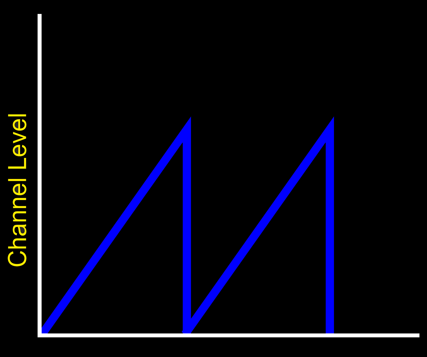
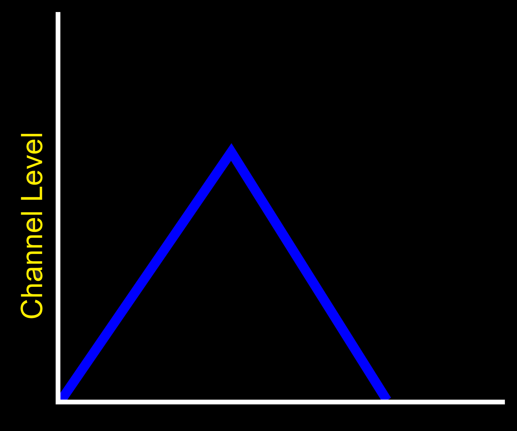
The output level increases from 0% to the selected limit and then instantly drops back to 0% The adjustment control controls how fast the level goes up, with values from 1 to 99. The second value, is the pulse feel, that allows you to adjust the sensation of the pulse stream, from soft to spiky, with values from 1 to 99. With different values for the left and right channels levels, it is possibly to adjust the synchronicity of the outputs, with one channel rising and dropping faster than the other.
Since the cycle runs from 0% to what ever level you have set, say 33%, the cycle will be shorter and thus faster with smaller level values. So 0-10% will appear to cycle faster than 0-50%.
TIP : If you want both channels to cycle together with the same settings, use the Join Controls Option before you set the mode.
To Select Wave Mode
To select the Wave Mode, press the Select Button once and rotate the Adjust Control to select the mode

Now press the Select Button to choose the currently displayed mode.

The screen shows the mode on the top line, then the Step Speed and Output Feel (50:50). On the bottom line the Channel A Level, Output Map, Output Power Setting, Battery Level and Channel B Level is shown.
Changing Values
In Wave mode the output rises from 0% to the currently selected Level for the channel and then drops back to 0% before repeating again.
So if Channel A is set to 10%, then the level will increase from 0% to 10% in a number of steps and then instantly dropping back to 0%. The speed of the increase is controlled by the Adjust Control and the Ramp Speed Option. Because the channel drives are independent, it is possible to have one channel rising and dropping at a different rate to the other. As Wave cycles between zero and the Channel level set, there is no output with levels set to 2% or below.
The rate of change is from around 1 second to 0.02 seconds with Time Warp set to x1, increasing to around 35 seconds to 0.5 seconds with Time Warp set to x32 The amount of each step is controlled by the Ramp Speed setting.
WARNING THIS IS A BETA RELEASE MANUAL NOT FOR 2.106 FIRMWARE
The output level increases from 0% to the selected limit and then reverses and gradually drops back to 0% The adjustment control controls how fast the level goes up or down, with values from 1 to 100. The second value, is the pulse feel, that allows you to adjust the sensation of the pulse stream, from soft to spiky, with values from 1 to 100. With different values for the left and right channels levels, it is possibly to adjust the synchronicity of the outputs, with one channel rising and dropping faster than the other.
To Select Waterfall Mode
To select the Waterfall Mode, press the Select Button once and rotate the Adjust Control to select the mode

Now press the Select Button to choose the currently displayed mode.

The screen shows the mode on the top line, then the Step Speed and Output Feel (50:50). On the bottom line the Channel A Level, Output Map, Output Power Setting, Battery Level and Channel B Level is shown.
Changing Values
In Waterfall mode the output rises from 0% to the currently selected Level for the channel and then gradually drops back to (at the same rate as the increase) 0% before repeating again.
So if Channel A is set to 10%, then the level will increase from 0% to 10% in a number of steps, and then gradually back down to 0% The Speed of the increase is controlled by the Adjust Control and the Ramp Speed Option. Because the channel drives are independent, it is possible to have one channel rising and dropping at a different rate to the other. As Waterfall cycles between zero and the Channel level set, there is no output with levels set to 2% or below.
The rate of change is from around 1 second to 0.02 seconds with Time Warp set to x1, increasing to around 35 seconds to 0.5 seconds with Time Warp set to x32 The amount of each step is controlled by the Ramp Speed setting.
WARNING THIS IS A BETA RELEASE MANUAL NOT FOR 2.106 FIRMWARE
The pulse rate increases and then drops to nearly continuous producing a synchronised ‘squeeze’ sensation. Both Channel A and Channel B pulse at the same rate. The adjustment control controls how fast the pulse rate goes up or down with values from 10 to 100. The second value, is the pulse feel, that allows you to adjust the sensation of each individual pulse, from soft to spiky, with values from 1 to 100.
To Select Squeeze Mode
To select the Squeeze Mode, press the Select Button once and rotate the Adjust Control to select the mode

Now press the Select Button to choose the currently displayed mode.

The screen shows the mode on the top line, then the Step Speed and Output Feel (50:50). On the bottom line the Channel A Level, Output Map, Output Power Setting, Battery Level and Channel B Level is shown.
Changing Values
In Squeeze mode the pulse speed rises from slow to fast producing what feels to many as a squeezing action. Both Channel A and Channel B 'squeeze' at the same rate.
To Change the range of squeeze, use the Adjust Control. Low values will give a slower squeeze rate. To change the Feel, press and hold the Select Button and rotate the Adjust control.
The time each cycle takes can be extended by the use of the Time Warp control. the speed of increase or decrease can be adjusted with the Ramp Speed setting.
WARNING THIS IS A BETA RELEASE MANUAL NOT FOR 2.106 FIRMWARE
The pulse rate increases and then drops to 0 (continuous). This is similar to Squeeze, but with a immediate drop in the pulse rate at the end of the cycle. The Adjust Control controls how fast the pulse rate goes up or down with values from 10 to 100. The second value, is the pulse feel, that allows you to adjust the sensation of each individual pulse, from soft to spiky, with values from 1 to 100.
To Select Milk Mode
To select the Milk Mode, press the Select Button once and rotate the Adjust Control to select the mode

Now press the Select Button to choose the currently displayed mode.

The screen shows the mode on the top line, then the Step Speed and Output Feel (50:50). On the bottom line the Channel A Level, Output Map, Output Power Setting, Battery Level and Channel B Level is shown.
Changing Values
In Milk mode the pulse speed rises from slow to fast??? producing what feels to many as a squeezing action. Channel A and Channel B 'squeeze' at alternates rates, giving a milking action.
To Change the range of squeeze, use the Adjust Control. To change the Feel, press and hold the Select Button and rotate the Adjust control.
The time each cycle takes can be extended by the use of the Time Warp control. the speed of increase or decrease can be adjusted with the Ramp Speed setting.
A continuous mode with the pulse feel cycling between two values. Nice and relaxing. Adjustments values are between 1 and 99.
To Select Throb Mode
To select the Throb Mode, press the Select Button once and rotate the Adjust Control to select the mode

Now press the Select Button to choose the currently displayed mode.

The screen shows the mode on the top line, then the Feel Adjustment Value. On the bottom line the Channel A Level, Output Map, Output Power Setting, Battery Level and Channel B Level is shown.
Changing Values
In Throb mode the pulse feel rises from soft to Hard producing what feels to many as a squeezing or kneeding action. Both Channel A and Channel B 'Throb' at the same rate.
To Change the range of squeeze, use the Adjust Control.
The Adjust Control on its own controls the lower limit of the cycle. Pressing and holding the Select Button and rotating the Adjust Control will control the upper limit of the cycle. If you attempt to increase the lower limit beyond the higher limit then the upper limit will automatically change, as will the lower limit if you attempt to change the upper limit below the lower limit.
The Ramp Speed setting controls how fast the feel will change. The Time Warp control has no effect in this mode.
WARNING THIS IS A BETA RELEASE MANUAL NOT FOR 2.106 FIRMWARE
Similar to Throb, Thrust is a continuous mode. with the pulse feel cycling between 10 and the adjustment value and then back to 0. Adjustments values are between 10 and 100.
To Select Thrust Mode
To select the Thrust Mode, press the Select Button once and rotate the Adjust Control to select the mode

Now press the Select Button to choose the currently displayed mode.

The screen shows the mode on the top line, then the Feel Adjustment Value. On the bottom line the Channel A Level, Output Map, Output Power Setting, Battery Level and Channel B Level is shown.
Changing Values
In Thrust mode the pulse speed rises from slow to fast??? producing what feels to many as a squeezing action. Both Channel A and Channel B 'squeeze' at the same rate.
To Change the range of squeeze, use the Adjust Control.
The Adjust Control on its own controls the lower limit of the cycle. Pressing and holding the Select Button and rotating the Adjust Control will control the upper limit of the cycle. If you attempt to increase the lower limit beyond the higher limit then the upper limit will automatically change, as will the lower limit if you attempt to change the upper limit below the lower limit.
The Ramp Speed setting controls how fast the feel will change. The Time Warp control has no effect in this mode.
WARNING THIS IS A BETA RELEASE MANUAL NOT FOR 2.106 FIRMWARE
A continuous mode with the pulse feel cycling between 10 and the adjustment value. Feel values are reversed on each channel. Nice and relaxing. Adjustments values are between 10 and 100.
To Select Cycle Mode
To select the Step Mode, press the Select Button once and rotate the Adjust Control to select the mode

Now press the Select Button to choose the currently displayed mode.
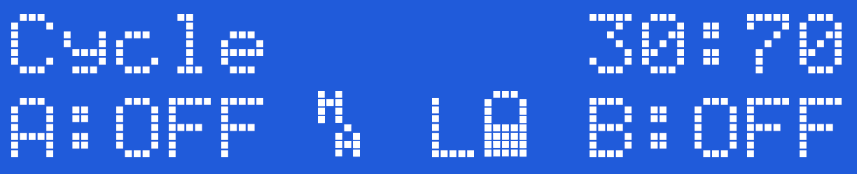
The screen shows the mode on the top line, then the Step Delay Value, and the Feel Adjustment Value (50:50). On the bottom line the Channel A Level, Output Map, Output Power Setting, Battery Level and Channel B Level is shown.
Changing Values
?????
Affected by Timewarp?? and ramp?? speed settings.
WARNING THIS IS A BETA RELEASE MANUAL NOT FOR 2.106 FIRMWARE
New twist mode
??????????????
To Select Twist Mode
To select the Twist Mode, press the Select Button once and rotate the Adjust Control to select the mode

Now press the Select Button to choose the currently displayed mode.

The screen shows the mode on the top line, then the Step Delay Value, and the Feel Adjustment Value (50:50). On the bottom line the Channel A Level, Output Map, Output Power Setting, Battery Level and Channel B Level is shown.
Changing Values
?????
Affected by Timewarp?? and ramp?? speed settings.
WARNING THIS IS A BETA RELEASE MANUAL NOT FOR 2.106 FIRMWARE
The random mode is designed to produce a random pulse output the adjustment control allows the user to adjust the ‘randomness’ of the pulse range, from 2 to 100. Lower numbers give a much faster random pulse stream. The second value, is the pulse feel, that allows you to adjust the sensation of each individual pulse, from soft to spiky.
To Select Random Mode
To select the Random Mode, press the Select Button once and rotate the Adjust Control to select the mode

Now press the Select Button to choose the currently displayed mode.

The screen shows the mode on the top line, then the Random Delay Value, and the Feel Adjustment Value (50:50). On the bottom line the Channel A Level, Output Map, Output Power Setting, Battery Level and Channel B Level is shown.
Changing Values
Random is a pulsed mode, with random on time, and random off time, the random value is between 0 and the Random Delay Value. A higher Random Delay value of say 100 will give more randomness than a value of 10.
Looking for lonnder/wider delay times? use the Timewarp setting.
WARNING THIS IS A BETA RELEASE MANUAL NOT FOR 2.106 FIRMWARE
Step mode is designed to step the output up in individual steps, allowing the subject to get used to the current level, before the output is stepped up to the next level. The output steps between 0 and the current Channel level with a delay between step controlled by the Adjust Control, from 1 to 100.
The second value, is the pulse feel, that allows you to adjust the sensation of the pulse stream, from soft to spiky. Each step is set to 1%. Lower values, give a faster step. Because of the delay of the programmed step, any changes in output level, will only occur at the next step change.
To Select Step Mode
To select the Step Mode, press the Select Button once and rotate the Adjust Control to select the mode

Now press the Select Button to choose the currently displayed mode.

The screen shows the mode on the top line, then the Step Delay Value, and the Feel Adjustment Value (50:50). On the bottom line the Channel A Level, Output Map, Output Power Setting, Battery Level and Channel B Level is shown.
Changing Values
Channel A and Channel B Level controls set the limit of the step. The Difference between 0 and the LEvels set is divided by 8 and this is the value of each step. The time each step changes is controlled by the Adjust Control, To Change the feel of the steps, Press and hold the Select Button and rotate the Adjust Control.
Effected by Timewarp?? and ramp?? speed settings.
WARNING THIS IS A BETA RELEASE MANUAL NOT FOR 2.106 FIRMWARE
The training mode is similar to the Step Mode , but the steps are much bigger, requiring the subject to learn to ‘enjoy’ each step before the output is stepped up to the next level. The output steps between 0 and the current Channel level. Each step is 1/12 of the total Channel level or 1% if the channel level is set to 12% or lower, so if Channel A is set to 48%, the steps will be 4%, 8%, 12% up to 48%, and then dropping to zero. The Adjust value allows you to adjust the delay between level changes, from 2??? to 100. The second value, is the pulse feel, that allows you to adjust the sensation of the pulse stream, from soft to spiky. Lower values, give a faster step. Because of the delay of the programmed step, any changes in output level, will only occur at the next step change.
To Select Training Mode
To select the Training Mode, press the Select Button once and rotate the Adjust Control to select the mode

Now press the Select Button to choose the currently displayed mode.

The screen shows the mode on the top line, then the Step Delay Value, and the Feel Adjustment Value (50:50). On the bottom line the Channel A Level, Output Map, Output Power Setting, Battery Level and Channel B Level is shown.
Changing Values
Channel A and Channel B Level controls set the limit of the step. The Difference between 0 and the LEvels set is divided by 8 and this is the value of each step. The time each step changes is controlled by the Adjust Control, To Change the feel of the steps, Press and hold the Select Button and rotate the Adjust Control.
Effected by Timewarp?? and ramp?? speed settings.
WARNING THIS IS A BETA RELEASE MANUAL NOT FOR 2.106 FIRMWARE
Tickle mode is designed to be a sensation mode rather than a harder feeling program. In the same way you would not expect a harsh beating from a feather, Tickle gives a light controllable touch that can tantalise.
Selecting Tickle Mode
To select the Tickle Mode, press the Select Button once and rotate the Adjust Control to select the mode

Now press the Select Button to choose the currently displayed mode. In this case Tickle Mode.

The screen shows the mode (Tickle) and Feel (50) on the top line, then, on the bottom line the Channel A Level, Output Map, Output Power Setting, Battery Level and lastly the Channel B Level.
Using Tickle
Increase the Channel Level above 1%. Now rotate the Adjust control, you should see the active channel LED flicker. This is Tickle mode in action. Output in Tickle mode is ONLY ACTIVE when the Adjust knob is being rotated and the level for a channel is greater than 0%. When you stop rotating the Adjust control, The output will stop.
Tickle mode is exactly what it says - a 'Tickle'. If you want a more pronounced sensation, then increase the level, adjust the Feel (Press and Hold the select button while turning the Adjust control to change the Feel Level), spin the adjust control faster and or change the Tickle Response via the Tickle Level Menu.
Output levels are control by the Channel Level controls and would normally need to be set higher that you would normally use on other modes.
Feel Control
To adjust the Feel in Tickle mode. Press and Hold the Select Button while turning the Adjust Control. The feel value on the screen will then change. The range is from 1-100.
Tickle mode is not accessible from Commander.
WARNING THIS IS A BETA RELEASE MANUAL NOT FOR 2.106 FIRMWARE

The stereo input allows you to use the line in input to stimulate the outputs, from a source such as a CD/MP3 players. The left audio channel activates the A output channel, the level indicated by the A: and the left hand bar graph, whilst the B channel level is indicated by the B: and the right hand bar graph the right audio channel activates the B output channel. The bargraph display indicates the relative input level of each channel.
Do NOT connect your audio device to the 2B before switching to any audio input
How it works
The A and B controls control the percentage of the audio drive that is passed through to the outputs. The relationship between the Input and the output is complex as we use a unique DSP (Digital Signal Processor) to provide you with a more interesting output compared to StereoStim devices.
The adjust control allows you to change the speed of the response of the stereo system, indicated by the third value. A low value gives a smoother response, a higher values gives a sharper response.
You should aim for maximum movement in the bar graph. If the bar graphs are ‘full’ you should reduce the output volume of the device you are driving the 2B with, if there appears to be no bar graph then turn the volume control up.
To select Stereo Mode
Press the Select Button and rotate the Adjust Control to show

Press the Select Button again to select the Stereo mode
The display shows two bar graphs on the top line, together with the Adjust value. The bottom line shows the Channel A and channel B Level. The battery status is not show in audio modes. The Stereo mode does not make use of the output map, hence the reason it is not shown.
Overdriving the Input
The input level is controlled by your audio source. It is suggested you adjust your input source to ensure the input is not being over driven. (the bar graphs on the 2B should not appear as a solid stationary bar.Over driving the input does not increase the output level, and it does loose some of the nuances of the audio input.
Response Adjustment
The adjustment control changes the response of the DSP (Digital Signal Processor). Since the 2B is designed to operate with complex audio sources, the response control gives allows you to 'tune' the response of the 2B more to your own tastes. Experiment to find what works for you.
To exit the stereo mode, simply press the Adjust button.
Laptop Detection Issues
Some Laptops may incorrectly detect the Digital link on the shared audio port when running in other modes. If this is the case, switch to Stereo Mode BEFORE connecting the audio cable to your laptop. In other words...
Do NOT connect your audio device to the 2B before switching to any audio input
WARNING THIS IS A BETA RELEASE MANUAL NOT FOR 2.106 FIRMWARE
WARNING THIS IS A BETA RELEASE MANUAL NOT FOR 2.106 FIRMWARE

The stereo input allows you to use the line in input to stimulate the outputs, from a source such as a CD/MP3 players. The left audio channel activates the A output channel, the level indicated by the A: and the left hand bar graph, whilst the B channel level is indicated by the B: and the right hand bar graph the right audio channel activates the B output channel. The bargraph display indicates the relative input level of each channel.
How it works
The A and B controls control the percentage of the audio drive that is passed through to the outputs. The relationship between the input and the output is complex as we use a unique DSP (Digital Signal Processor) to provide you with a more interesting output compared to StereoStim devices.
The Advanced Stereo mode also utilises the Output Mapping system giving you even more variation. If you want to use the original (2.106 firmware) drive system, then consider using the Stereo Mode.
The adjust control allows you to change the speed of the response of the stereo system, indicated by the third value. A low value gives a smoother response, a higher values gives a sharper response.
You should aim for maximum movement in the bar graph. If the bar graphs are ‘full’ you should reduce the output volume of the device you are driving the 2B with, if there appears to be no bar graph then turn the volume control up.
Do NOT connect your audio device to the 2B before switching to any audio input
To select Advanced Stereo Mode
Press the Select Button and rotate the Adjust value to show

Press the Select Button again to select the Stereo mode
The display shows two bar graphs on the top line, together with the Adjust Control. The bottom line shows the Channel A and channel B Level. The battery status is not show in audio modes. The Stereo mode does not make use of the output map, hence the reason it is not show.
Overdriving the Input
The input level is controlled by your audio source. It is suggested you adjust your input source to ensure the input is not being over driven. (the bar graphs on the 2B should not appear as a solid stationary bar.Over driving the input does not increase the output level, and it does loose some of the nuances of the audio input.
Response Adjustment
The adjustment control changes the response of the DSP (Digital Signal Processor). Since the 2B is designed to operate with complex audio sources, the response control gives allows you to 'tune' the response of the 2B more to your own tastes. Experiment to find what works for you.
To exit the Advanced Stereo mode, simply press the Adjust button.
Laptop Detection Issues
Some Laptops may incorrectly detect the Digital link on the shared audio port when running in other modes. If this is the case, switch to Advanced Stereo Mode BEFORE connecting the audio cable to your laptop. In other words....
Do NOT connect your audio device to the 2B before switching to any audio input
WARNING THIS IS A BETA RELEASE MANUAL NOT FOR 2.106 FIRMWARE
WARNING THIS IS A BETA RELEASE MANUAL NOT FOR 2.106 FIRMWARE

The Microphone Mode uses the internal microphone to stimulate the outputs. As the internal microphone is a mono source, both the outputs are stimulated together. The stereo bargraph display indicates the relative input level. The A and B controls control the percentage of the input from the microphone that is passed through to the outputs, and the Adjust Control set the level at which the 2B will respond to the outputs. A low adjust level will make the 2B more responsive.
To select Microphone Mode
Press the Select Button and rotate the Adjust Control to show

Press the Select Button again to select the Microphone mode
The display shows two bargraphs on the top line, together with the Adjust Level Control. The bottom line shows the Channel A output Level, the Current Output Map. the Microphone sensitivity setting, and the Channel B level. The battery status is not show in audio modes.
The built in microphone has no external connections, and is sensitive enough to pickup a conversation (depending on what level the microphone is set to) from several feet away. Obviously this depends on the ambient level of sound. The placement of the microphone is close to the channel A control knob.
Microphone Adjustment
The Microphone Adjust control changes the response of the DSP (Digital Signal Processor) system, giving you even more control over the response of the Microphone. Because the DSP code is designed to create sensation from complex audio sources such as music or your voice, the effects of the adjust control will vary depending on the audio used.
Overdriving
It is possible to overdrive the audio section of the 2B. This results in a reduction of sensation as the nuances of the audio input are lost. If the display appears to be a solid bar, then you are probably overdriving the 2B. Either move the 2B away from the audio source, or change the Microphone Level selection.

To Exit the Microphone Mode
In order to exit from the microphone mode press the select button, or turn the unit off.
Microphone sensitivity
The overall sensitivity of the Microphone can be adjusted with the Microphone Level option, with settings allowing x1 (normal), x2, x4, x8 and x16 responses. Higher levels might be inoperable in noisy environments.
WARNING THIS IS A BETA RELEASE MANUAL NOT FOR 2.106 FIRMWARE
WARNING THIS IS A BETA RELEASE MANUAL NOT FOR 2.106 FIRMWARE
The inbuilt microphone system can be made more sensitive by selection the level. x1 is normal, increased sensitivity is available from x1 to x16. Higher levels many not be operable in a noisy environment.
To Change the Microphone Level
Press the Select Button. on the front of your 2B. This will take you into the mode select option system. The initial mode show will depend on what mode you where in before pressing the Select Button.
Now rotate the central Adjust Knob clockwise until you can see the 'Mic Level' Option on the LCD screen.

Press the Select Button. The exact microphone sensitivity level shown on initial entry into the microphone level selection is set by what ever was last set (It is one of the values that are retained when the 2B is switched off).

By rotating the Adjust Knob you can cycle between the different microphone sensitivity.




Once you have chose the level you require, press the Select button to engage the sensitivity. The 2B will now jump back to the Mode select screen,
with the Microphone Mode pre chosen. Now press the Select Button again to choose Microphone mode, or rotate the Adjust Control to choose another mode.
WARNING THIS IS A BETA RELEASE MANUAL NOT FOR 2.106 FIRMWARE
WARNING THIS IS A BETA RELEASE MANUAL NOT FOR 2.106 FIRMWARE
Time warp allows you to increase the time ranges certain modes use on the 2B. Time Warp offers values from x1 to x32. In other words, if a particular mode cycled at 1 pulse per second with time warp that could increase the delay between pulses to 2 seconds with Time Warp set to x2 and around 32 seconds with time Warp set to x32
Changing TimeWarp Values
To change the TimeWarp values, press the Select Button once and rotate the Adjust Control to select Time Warp

Now press the Select Button to enter Time Warp selection.

Now rotate the Adjust Control to show the desired Timewarp value, displayed as x1 to x32, and then press the Select Button to select the TimeWarp Value shown.
The screen will now return to the previous mode set.
Values
Time Warp Values range from x1, the Default to x32
Active Modes
Timewarp setting effect the following modes
In other modes the TimeWarp value has no effect.
The Timeward setting is retained when the 2B is switched off. Performing a Factory Reset will reset the Time Warp value to x1.
WARNING THIS IS A BETA RELEASE MANUAL NOT FOR 2.106 FIRMWARE
A number of settings are retained when your 2B unit is switched off. These settings are retained even if the battery is removed. To clear these settings select the factory reset option. The options that are changed during a factory reset are
- Mode is set to Pulse
- Join controls are switched off.
- Power Level is set to Low
- Output Map is set to A
- Microphone is set to x1
- Warp Factor is set to x1
- Ramp Speed is set to XXX
- Tickle Factor is set to XXXX
It is important to perform a factory reset whenever you update the firmware on a 2B. Failure to perform a factory reset after updating the Firmware may result in unusual or incorrect operation of your 2B.
To perform a Factory Reset
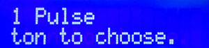
Press the Select Button. on the front of your 2B. This will take you into the mode select option system.
Now rotate the central Adjust Knob clockwise until you can see the 'Full Reset' Option on the LCD screen.
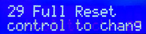 Now press the Select Button to choose the Full Reset Mode.
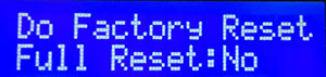
If you do not wish to perform a factory reset at this time, then simply press the Select Button and the factory reset will be cancelled. If you do with to continue, then rotate the Adjust Knob to show the following display;
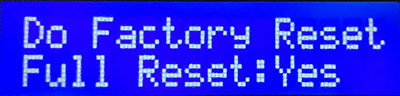 and now press the Select Button. The factory reset will be performed and the 2B will be returned to mode select.
Video - How to Factory Reset a 2B
WARNING THIS IS A BETA RELEASE MANUAL NOT FOR 2.106 FIRMWARE
Joining Controls (A+B Mode)
When you first switch your 2B unit on, both the Channel A and Channel B controls are independent. However If you select the join mode (A+B) then the two controls become linked, giving you effectively one handed operation.
When you turn the Channel A control up, the Channel B value will also rise, if you turn it down, the Channel B channel will reduce as well. If you adjust the Channel B control when the join mode is active, then you can adjust the relative levels of each channel.
To Join or unjoin the Controls
Press the Select Button. on the front of your 2B. This will take you into the mode select option system.The exact mode display will depend on your current mode.
Now Rotate the Adjust Control until you see 25 A&B Chan Link

Press the Select Button,

now rotate the Adjust Control until you see either On

or Off
Now press the Select Button to select the your chosen join status.
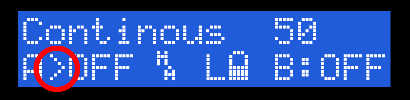
You can see the current join status from the display. If join is active a '>' will be shown to show the current master control, in this case Channel A.
WARNING THIS IS A BETA RELEASE MANUAL NOT FOR 2.106 FIRMWARE
The Tickle mode has an adjustable sensitivity allowing you to control the output in Tickle mode from a tickle to a more pronounced sensation. Soft is normal, increased sensitivity is available from Soft, Low, Medium and High. Higher levels will feel more intense.
To Change the Tickle Level
Press the Select Button. on the front of your 2B. This will take you into the mode select option system. The inital mode show will depend on what mode you where in before pressing the Select Button.
Now rotate the central Adjust Knob clockwise until you can see the 'Tickle Level' Option on the LCD screen.

Press the Select Button. The exact tickle level shown on initial entry into the tickle level selection is set by what ever was last set (It is one of the values that are retained when the 2B is switched off).

By rotating the Adjust Knob you can cycle between the different tickle levels. Soft is the lowest level, High is the highest.



Once you have chose the level you require, press the Select button to engage the level. The 2B will now jump back to the mode select screen,
with Tickle Mode pre chosen. Now press the Select Button again to choose Tickle mode, or rotate the Adjust Control to choose another mode.
WARNING THIS IS A BETA RELEASE MANUAL NOT FOR 2.106 FIRMWARE
Certain modes, such as Wave, WaterFall and Throb and Thrust use inbuilt cycling between settings to achieve the desired sensation. The Ramp Speed allows you to control the rate of change, from Slow to Xtrm (Extreme).
Changing Ramp Speed Values
To change the Ramp Speed values, press the Select Button once and rotate the Adjust Control to select Ramp Speed

Now press the Select Button to enter the Ramp Speed selection.

Rotate the Adjust know to choose the Ramp speed you wish to use and then press the Select Button. You can now choose another mode
| Ramp Speed Selected | Wave & Waterfall modes | |
|
Slow | Level changes by 1% each step |
 |
Medium | Level changes by 2% each step |
 |
Fast Step | Level changes by 4% each step |
 |
Extreme | Level changes by 8% each step |
WARNING THIS IS A BETA RELEASE MANUAL NOT FOR 2.106 FIRMWARE
What is an output map?
Output maps are a way of offering a different response between the control level and the output level. Some people want more control at one end, others want more control at higher levels, and some might want something in the middle. Many modern cars have a similar system - allowing the car to be more responsive for 'Sport' driving or provide more torque for off roading. Another way of looking at output maps is think if the gears in the car - the engine revs over a fixed range, but the gears provide changes in torque, so first gear allows you to pull away, while fifth gear allows you to cruise, all from the same engine.
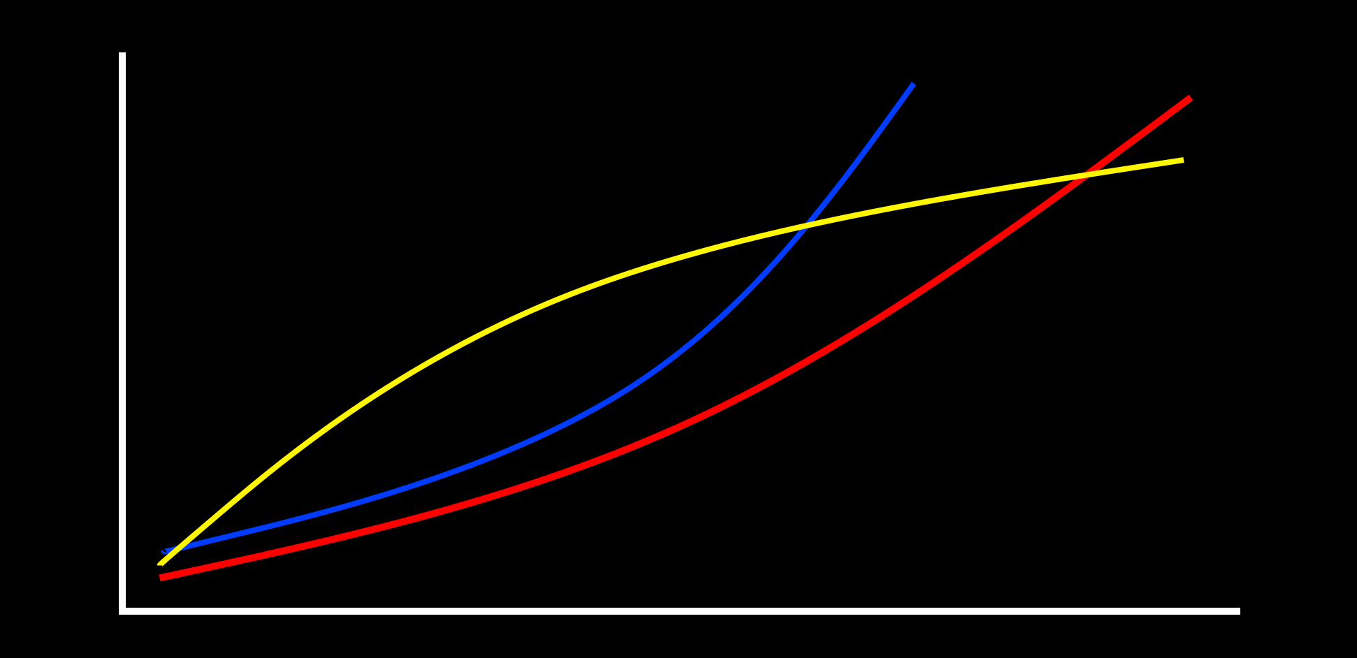
With the 2B we offer 3 output maps, where the level set on the display (66%) ‘maps’ to a specific level feeling for each level chosen. This means you can select a map more suited to the sensations you enjoy. Map A will give a linear response and feels more powerful, faster, Map B starts slower giving people who want more control over the lower end, and Map C is similar to the classic 2.106 firmware. The maps can also feel different depending on what power setting you are using. The human body does not respond to E-Stim in a linear manner - 40% will not feel twice as powerful as 20%, so it is a case of experiment and find out what works for you.
The image above is a rough graphical representation to indicate different maps - it is not accurate!!.
To Change the Output Map
Press the Select Button. on the front of your 2B. This will take you into the mode select option system. The initial mode shown will depend on what mode you where in before pressing the Select Button.
Now rotate the central Adjust Knob clockwise until you can see the 'Output Map' Option on the LCD screen.

Press the Select Button. The exact Output Map shown on initial entry into the output map selection is set by what ever was last set (It is one of the values that are retained when the 2B is switched off).

By rotating the Adjust Knob you can cycle between the different output maps A-C. The output map is only selected once you press the Select Button.


Once you have chosen the output map you require, press the Select button to engage the map. The 2B will now jump back to the mode select screen,
Now select the mode you wish to use and continue. The current output map will display as a small icon on the bottom line.

The 2B will use the same output map until you change it, or you perform a Factory Reset.
WARNING THIS IS A BETA RELEASE MANUAL NOT FOR 2.106 FIRMWARE
The 2B is capable of operating in multiple power levels, indicated by a ‘L’ , ‘H’ or ‘D’ in the display (centre bottom line). This gives you a wide range of play compared to single level units as each power setting is controllable from 0-100%. These is some overlap between low and High, so experiment to find a level suitable for your needs.If you don't want the risk of going too high, then stick to using the LOW setting. If you want the flexibility of using the entire range of the 2B, then Dynamic is what you should consider.
Don't forget than using an E-Stim Systems Power supply will automatically give you around a 30% increase in power, and will last far longer than a battery.
To Change the Power Level
Press the Select Button. on the front of your 2B. This will take you into the mode select option system. The initial mode show will depend on what mode you where in before pressing the Select Button.
Now rotate the central Adjust Knob clockwise until you can see the 'Power Level' Option on the LCD screen.

Press the Select Button. The exact Power level shown on initial entry into the Power level selection is set by what ever was last set (It is one of the values that are retained when the 2B is switched off).

By rotating the Adjust Control you can cycle between the different power levels.


Once you have chosen the power level you require, press the Select button to engage the level. The 2B will now jump back to the mode select screen,
Choose your mode and continue to play with the new power setting.
Power Levels
As mentioned above, once you have selected the power level, the 2B will stay in the same power setting until either you select the other power mode, or perform a Factory Reset.
The currently selected power mode is displayed on all program screens as a ‘L’, ‘H’ or ‘D’.
Dynamic Mode
Dynamic mode merges the power settings of Low and High to create a single power setting that at low values is similar to low values on ‘L’ and at high values is similar to ‘H’ settings, so in dynamic mode there is no need to switch between ‘L’ and ‘H’. The actual level is dependent on the tracking source selected, So a selected source will ‘bias’ the power setting. Setting of the bias source is via a menu option and the options are
Max The maximum channel value shown is used. So if Channel A is set to 10% and Channel B is set to 80% the bias source will be B.
Avg The Average of Channel A and Channel B are used.
A Channel A is used
B Channel B is used.
To Change the Dynamic Bias Source
Press the Select Button. on the front of your 2B. This will take you into the mode select option system. The initial mode show will depend on what mode you where in before pressing the Select Button.
Now rotate the central Adjust Knob clockwise until you can see the 'Dynamic Bias' Option on the LCD screen.

Press the Select Button. The exact dynamic bias shown on initial entry into the bias selection is set by what ever was last set (It is one of the values that are retained when the 2B is switched off).

By rotating the Adjust Control you can cycle between the different bias source settings.



Once you have chosen the bias source you require, press the Select button to engage the bias source. The 2B will now jump back to the mode select screen,
The power selection and bias setting are both remembered when the 2B is powered off, and can be reset to the default ‘MAX’ by using a Factory Reset. The current bias setting is not shown on the main display screen, and is only active when the Power Setting is set to Dynamic.
WARNING THIS IS A BETA RELEASE MANUAL NOT FOR 2.106 FIRMWARE
The E-Stim Systems 2B contains on board programs, the 'Firmware', that can be updated by the user. To do so you will need a PC or Mac computer running Windows or MacOS, and a Digital Link Interface system, available from E-Stim Systems. The software required to perform the update 'UpLink' is only available as part of the Digital Link Interface.
Where to Buy
Digital Link Pack (UK/ Europe)
Digital Link Pack (US / Rest of the World)
Or any good stockist of E-Stim Systems Products.
WARNING THIS IS A BETA RELEASE MANUAL NOT FOR 2.106 FIRMWARE
For more details on how to control your E-Stim Systems 2B from a computer visit https://e-stim.info/commander
E-Stim Commander allows control via a PC, as well as the ability to record and playback 'sessions' from your PC or Mac.
WARNING THIS IS A BETA RELEASE MANUAL NOT FOR 2.106 FIRMWARE
It is possible to control the E-Stim Systems 2B over the internet with the optional Digital Link Interface. For more details of the Systems see our E-Stim Connect pages at https://e-stim.online.
E-Stim Connect is a secure and simple to use web browser based interface. Because it is web based, it is useable from any modern computer or mobile device with an internet browser and internet access.
All images and text within this manual are ©E-Stim Systems Ltd 2007-2021
EBox™, EBox 2B™, 2B™, Uplink™, Commander3™ Commander4™, E-Stim Connect™ and derivative terms are trademarks of E-Stim Systems Ltd.
All rights reserved. E & OE.
Do not use solvents to clean your 2B. A gentle wipe with a soft cloth is all that is needed. It is not possible to sterilise the control unit.
In the event your 2B is not going to be used for long periods of time it is recommended you remove the battery.
US Regulatory Wireless Notice
This device compiles with Part 15 of the FCC Rules. Operation is subject to the following two conditions: (1) this device may not cause harmful interference, and (2) this device must accept any interference received, including interference that may cause undesired operation.
The FCC requires the user to be notified that any changes or modifications made to the device that are not expressly approved by E-Stim Systems Ltd may void the users authority to operate the equipment.
European Union Notice
Products bearing the CE marking comply with the EMC Directive (89/336/EEC), and the Low voltage Directive (73/23/EEC) issued by the Commission of the European Community.
Compliance with these directives implies conformity to the following European norms (in parentheses are the equivalent international standards and regulations.)
EN 55022 (CISPR 22) – Electromagnetic Interference, EN 55024 (IEC61000-4-2,3,4,5,6,8,11) – Electromagnetic Immunity, and EN 60950 (IEC 60950) – Product Safety.
This device may be used in the UK and all European Union Countries.
Type BF outputs
