Congratulations on purchasing a new E-Stim Systems Remote System. Given sufficient care your Remote System should give you many years of erotic electro stimulated pleasure. Before starting always read the instructions and ensure you are completely familiar with all of the controls and the safety warnings prior to use.
Quick Links
Key Features
- 10 adjustable control modes, with 27 output levels, all controlled from a custom 4 button digital Keyfob.
- Build in Dual Mode Audio driven trigger system with adjustable sensitivity and response.
- Adjustable Motion Sensor
- Uniquely digitally encoded Keyfob transmitters. Power units will not respond to other radio sources.
- Up to 100M range
- Learn mode allows multiple Keyfobs to be used in combination as well as multiple Power Units.
- New Dynamic Drive Single channel output allows the use of unipolar and bipolar electrodes.
- Current limited AC output to ensure safety and avoid the possibility of electrode polarisation.
|
SAFETY WARNING DO NOT CONNECT THE E-STIM SYSTEM REMOTE POWER UNIT OR ANY ELECTRICAL DEVICE TO ANY LOCATION ABOVE THE WAIST (ACROSS THE ARMS COUNTS AS ABOVE THE WAIST!), BUT ESPECIALLY DO NOT CONNECT ACROSS THE HEART, CHEST, NECK OR HEAD. DO NOT USE IF FITTED WITH A PACEMAKER OR ARE PREGNANT. REMEMBER YOU USE THIS DEVICE AT YOUR OWN RISK. YOU MUST READ AND UNDERSTAND THE USER MANUAL AND ALL OTHER INSTRUCTIONS BEFORE ATTEMPTING OPERATION. |
What's in the Pack?
Contents
 The new E-Stim Systems Remote system consists of two units, a small hand held 'key fob' style transmitter and the Power Unit radio receiver. The Power Unit is connected to an electrode that is attached or inserted into your subject, whilst the Keyfob transmitter provides the control from a distance of up to 50M (~150ft). The Pack also consists of a set of sticky pads, a 2mm/TENS connection cable, and a battery for the Power Unit (the battery for the Keyfob (CR2032) is already fitted). A quick guide is now also provided to give you a quick insight into the controls useful for when you don't have access to this online manual.
The distance over which the Power Unit will respond to the Keyfob transmitter is highly dependent on the environment, battery levels, and a number of other factors.
The remote allows 27 levels of output in 10 different modes. All controls including level and mode selection are via a simple up/down/select system on the Keyfob.
The system also allows the use of multiple Keyfobs and receivers. As each Keyfob generates a unique code, it is possible to 'teach' a Power Unit to respond to a number of Keyfobs, and conversely, it is also possible to have a number of receivers responding to a single Keyfob .
Before Use
Before you can use your E-Stim Systems Power Unit you need to ensure that the Power Unit has recognised and is responding to the Keyfob . If you insert a battery into the receiver, switch the unit on with no electrodes connected and press the red button on the Keyfob , two LED's should light on the receiver. The RX LED should flicker and the output LED should illuminate for the period of time the red button on the Keyfob is depressed.
If the activity LED flickers but the output LED does not illuminate, this indicates that the Power Unit has not recognised the Keyfob . In this case you need to follow the LEARN procedure.

Startup
On startup the Power Unit will perform a self test and display the battery level before selecting the last mode used. The remote system now remembers the previous mode the unit was in last time it was switched off, as well as the adjustment level. To reset the unit to Factory setting, follow the Factory reset procedure. The output level will always be set to zero when the Power Unit is switched on.
Using the Remote System
 Step 1 Fit the batteries The Keyfob is supplied with the battery fitted.
Step 2 Ensure the Keyfob is linked to the Power Unit (Learn Mode)
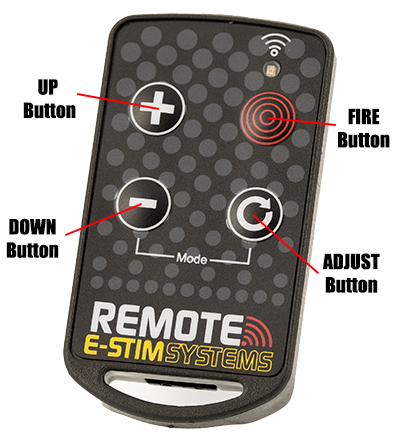
Familiarise yourself with the controls on the Keyfob.
Depending on the mode generally the UP button increases the output level, the DOWN button decreases the output level, and the FIRE button activates or overrides the output, depending on the current mode selected. The ADJUST Button provides adjustment in each mode. In Training Mode, the Down button gives 25% output, the Adjust button gives 50% output, the UP Button gives 75% out and and the Fire button gives 100% output.
Pressing both the DOWN and ADJUST buttons together will switch the unit into mode select. See Mode Control.
Holding a level button will increase or decrease the output in larger steps. If you hold a button down for more than around 30 seconds the Keyfob will automatically shut down to save batteries (This is designed to stop inadvertent activation of the Keyfob in a pocket). If this occurs, simply release the button and press again.
If the LED on the Keyfob appears dim, and range is reduced then the Keyfob battery may need to be replaced.
Connecting an electrode
Ensure the Power Unit is turned off, and connect a suitable electrode via the output socket. Connect an electrode to a suitable section of the body. (DO NOT CONNECT THE Power Unit UNIT OR ANY ELECTRICAL DEVICE TO ANY LOCATION ABOVE THE WAIST (ACROSS THE ARMS COUNTS AS ABOVE THE WAIST!), BUT ESPECIALLY DO NOT CONNECT ACROSS THE HEART, CHEST, NECK OR HEAD. DO NOT USE IF FITTED WITH A PACEMAKER OR ARE PREGNANT. REMEMBER YOU USE THIS DEVICE AT YOUR OWN RISK.
Turn the Power Unit on, the output LED should flash 4 times and automatically select the previous mode 1 and then press the red button. Your subject may feel a slight tingling sensation from the electrode site. If not increase the level and try again. Adjust the output level as required.
If you or your subject experiences any pain or discomfort then stop using immediately. If we recommend the use of conductive lubrication as any E-Stim device is potentially capable of causing burning when used on sensitive and or small contact areas at high output levels.
Always ensure all connections are secure and free from corrosion.
DO NOT SHORT CIRCUIT the output. DO NOT attempt to open the Power Unit unit. High voltages are present even when the unit is switched off and there are no user serviceable parts inside. Opening the Power Unit will invalidate your guarantee.
Fitting Batteries
Both the Keyfob and the Power Unit require batteries to operate. The Keyfob is supplied fitted with a battery, whilst the Power Unit unit needs to have a battery fitted (not supplied).
Fitting a battery (Power Unit)
Ensure the unit is switched off, and any electrodes connection cables are disconnected.
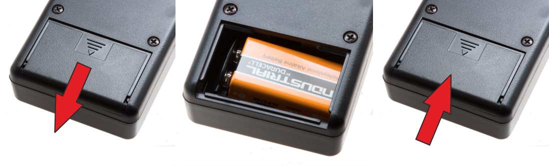
Turning the unit over press gently down on the center of the battery cover and slide the cover downwards.
Remove the old battery (if fitted) and replace with a fresh alkaline PP3. The battery connector is polarized so it should not be possible to connect the battery incorrectly, but ensure the polarity is correct before attempting connection.
Place the battery into the unit and replace the battery compartment cover. The cover will slide and then should then click into position.
Turn the unit over. The unit is now ready for operation.
Please note we do NOT recommend the use of Zinc Carbon or standard re-chargeable batteries in the E-Stim Systems Remote Power Unit. NiMh re-chargeable batteries, with a terminal voltage of 8.4V or above may be used with a possible reduction in output power.
In the event the Power Unit is not being used for a period of time, remove the battery to avoid any possible damage due to batter leakage.
Fitting a battery (Keyfob)
Before changing the battery ensure that the Power Unit unit is turned off and disconnected from any electrodes. The Keyfob is supplied with a battery (CR2032) installed.
In order to replace the battery, use a small 'Phillips' or cross head type screwdriver to unscrew the two screws on the back of the Keyfob , being careful not to loose them.
Open the case and gently remove the battery. Insert the new battery, noting the polarity marked by a '+' on the board and the battery and close the case.
Replace the screws and screw the Keyfob back together.
Check that the battery has been correctly inserted by pressing a button on the Keyfob (ensuring that any Power Unit in range is turned off). The yellow LED on the Keyfob should flash for the duration of the press. In the event that it does not, check you have replaced the battery correctly.
<changing battery keyfob pictures coming soon>
Level Control
in general most modes use the up and down buttons to control the level. When the level is selected the level is displayed on the status bar, unless you are in Discreet Mode. As we need to display 28 levels (we don't count zero as an actual level but it is), and need to show 4 different levels between each led. As the level increases the status display will show a growing bar graph with each successive LED flashing slowly, flashing faster, flashing even faster then switching to a solid glow. Then the next LED in the display will continue the cycle. As an example
| Slow Flash |  |
Level 1 |
| Medium Flash |  |
Level 2 |
| Fast Flash |  |
Level 3 |
| Solid | 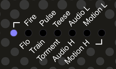 |
Level 4 |
Pressing and holding the UP or DOWN button will result in the level jumping to the next 4th step i.e. 4 8 12 16 20 etc etc. Pressing and holding the DOWN button continuously will eventually result in the zero level being reached, when a quick LED wipe will display.
In Discreet mode the level display is not shown.
Adjustment Control
Most modes have some form of adjustment. Repeatedly pressing and releasing the ADJUST button will cycle through the individual adjustment for the current mode.The effect of the actual adjustment will depend on the mode. The adjust dot display will show for a couple of seconds after the adjust button has been released.
If Discreet mode has been selected, the adjust dot display will not show.
Mode Control
Mode Selection
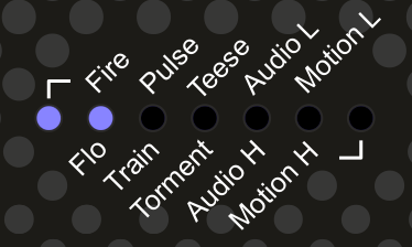
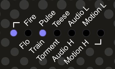
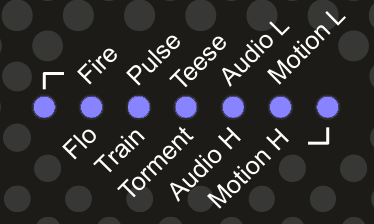
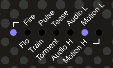
Pressing both DOWN and ADJUST buttons on the keyfob together AT THE SAME TIME will switch the Power Unit into mode selection mode, indicated by a two solid LEDs showing on the status bar on the receiver. The position of the LEDs will indicate the current mode, the left on the far left indicates modes on the top row can be selected, the LED on the far right indicates modes on the bottom row can be selected. A mode is not selected until the ADJUST button has been pressed.

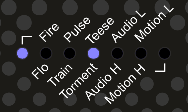
Pressing either the UP button or DOWN buttons will cycle up and down through the modes. Pressing the ADJUST button will activate the currently selected mode. The mode is not active until it has been selected. The mode is indicated by the left or right LED showing if you are on the top or bottom of the list of modes, and then a second LED showing the mode. As an example this is FIRE mode.
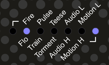
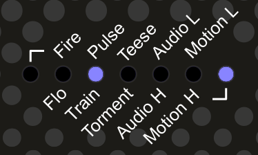
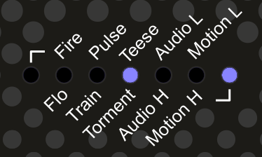
And this is Flo Mode
When the mode has been selected the status display will flash 3 times and then the output level is automatically set to zero. and the Adjust value set to 1. The current mode is remembered when the Power Unit is switched off.
The modes are as follows.
Fire Mode
The classic remote control mode. The UP and DOWN buttons control the output level (Zero to 27), whilst pressing the FIRE button will activate the output at the selected level as well as showing the output level on the Status display (unless you are in Discreet mode). The output will be active for the time the fire button is pressed, however the Keyfob will timeout after around 25 - 30 seconds cutting the output. The output LED will only be illuminated when the output is active. The Adjust button changes the feel of the output over 7 different values.
Flo Mode
A continuous output mode. The UP and DOWN buttons control the output level (Zero to 27), whilst pressing the FIRE button will give a boosted output 4 levels higher than the current setting (assuming there are any levels left and assuming your level is not set to zero. If the Power Unit is set to Level Zero then the output will not operate in boost mode when the fire button is pressed. ) Adjust cycles through several different ‘feelings’. Helix. In operation the Output LED will be on continuously. The Level output is not shown in Discreet Mode.
Pulse Mode
A pulsed output mode. The UP and DOWN buttons control the output level (Zero to 27), whist pressing the ADJUST button will cycle through 7 different pulse speeds from slow to fast. The FIRE button will override the output to give a continuous output. Level output is not shown in Discreet Mode.
Training Mode
The Classic 'Training Mode' No need to worry about what level the output is when you press the first button, as the outputs are preselected. DOWN Button gives 25% output, ADJUST 50% UP 75% and FIRE 100%. Assuming you are not using discreet mode the status display bar will indicate the output level.
 |
 |
 |
 |
| 25% | 50% | 75% | 100% |
Teese
 A continuous output mode with a rising feel, indicated by a moving LED on the status bar. Once a cycle is complete it starts from zero. UP and DOWN buttons control the level, and the FIRE button boosts the output 4 steps above the current output. The boost does not work if the output level is set to zero. The ADJUST button control the speed of the cycle with 7 different speeds available.
Torment
 A continuous output mode with a rising and dropping feel, indicated by a moving LED on the status bar. Once a cycle is complete the cycle reverses. UP and DOWN buttons control the level, and the FIRE button boosts the output 4 steps above the current output. The boost does not work if the output level is set to zero. The ADJUST button control the speed of the cycle with 7 different speeds available.
Audio Modes
Audio modes use sound to activate the output. The nature of the sound, the distance the sound source is from the Power unit , the level and the settings of the power unit in temrs of mode and adjustment selected all will effect how the sound is felt as an E-Stim sensation.
Audio Low Mode
Uses the inbuilt microphone to trigger the output. The ADJUST button controls the response, from highly sensitive to less sensitive. The Level controls UP and DOWN provide a multiple of the input so a maximum input with the level set to 27 (Full) will give the maximum output, where the same input with the level set to 14 will give half that output. The FIRE button artificially overrides the input giving the equivalent of a 100% input. Audio Low mode is not as sensitive as the Audio High Mode and is better used in more noisy environments.

 Audio High Mode
Uses the inbuilt microphone to trigger the output with a higher sensitivity than the Audio Input Low mode. UP and DOWN button control the level out the output, ADJUST controls the sensitivity and FIRE overrides the output.There are 7 levels of adjustment via the ADJUST control. The display is different to the Audio Low mode as it is a bargraph increasing from the left side giving a more sensitive display. The FIRE button artificially overrides the input giving the equivalent of a 100% input.
Motion Low Mode
Motion Sensitive mode. The UP and DOWN buttons control the output level (1-27), whilst pressing the FIRE button will override the motion trigger and activate the output. If the Power Unit is moved excessively then the output will trigger. WARNING it is very sensitive!!. In operation the output LED will flicker when the output is active.
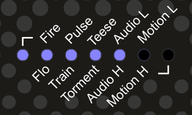
The motion sensor is very sensitive. In use the internal microprocessor counts the number of times the sensor is triggered and when this reaches a set level the output will fire. As the level builds up the bargraph will increase. Once all 7 bars are illuminated the Output will trigger. The trigger point is adjustable depending on the adjust setting. should no movement occur then the bargraph display will gradually decay over time. Pressing the FIRE button will override the output and ‘zap’ the subject, possibly causing even more movement!!
The motion sensor is active in any orientation.
Receiver
The Power Unit has two simple controls and 3 Displays.
Power Unit Displays
|
LED |
Use |
|
Output |
Indicates output activity and mode. In mode select mode, the number of flashes indicates the mode. On startup the Output LED will flash 3 times in quick succession. |
| Status Bar | Used to indicate the battery level, current output level, mode and adjustment |
|
RX |
Indicates Radio activity. Will also indicate when the Power Unit is in LEARN mode. Note that the RX LED will indicate activity when any compatible Keyfob is used within range, even if that Keyfob has not been learnt by the receiver. |
Power Unit Controls
|
Control Button |
Use |
|
Top Slide Switch |
Powers the unit on and off. |
|
Learn button (inside the battery compartment.) |
Used during the LEARN procedure. |
Power Unit Outputs
|
Output |
Use |
|
3.5mm mono socket |
Voltage output to electrode. |
LEARN Mode
What is it?
Learn mode allows the user to select which Keyfobs the Power Unit will respond to. It is possible to 'teach' a Power Unit to respond to up to 50 separate Keyfobs, and it is also possible to teach more than one Power Unit to respond to the same Keyfob .
The Power Unit is initially supplied with one Keyfob that is linked with the Power Unit during testing, and should operate 'out of the box'. Learn mode is generally only needed if you have purchased replacement or additional Keyfobs or receivers
The learn button is inside the battery compartment. Open the Battery Compartment, remove the battery, but do not disconnect it, and you should find the learn button inside. The learn button will only operate when the Power Unit has a battery connected and is powered on, so DO NOT DISCONNECT THE BATTERY.
Clearing the Power Unit memory
Clearing all Keyfobs. This will remove all Keyfob s from the Power Unit memory.
Remove the battery from the battery compartment but ensure that it is still connected. Turn the power unit on. Hold down the learn button for at least 10 seconds. The RX LED will illuminate. Release the learn button. The RX LED should now blink around 10 times and then stop. The memory has now been cleared.
Teaching the Power Unit to recognise a remote.
Remove the battery from the battery compartment but ensure that it is still connected. Turn the power unit on.
Press the learn button once. The RX LED should illuminate. Press a button on the Keyfob you wish to use with the receiver. The RX LED should now go out. press the button again. The RX LED should now blink several times. The Power Unit has now 'learnt' the Keyfob and will now respond to the Keyfob. Additional Keyfobs can also be added so one Power Unit will respond to more than one Keyfob. It is also possible to add a single Keyfob to more than one Power Unit giving even more possibilities.
Outputs
Connection to electrodes is via a single 3.5mm mono jack socket on the top of the receiver. Ensure the unit is switched off before inserting or removing the connection jacks to eliminate the possibility of either inadvertent electric shocks or short circuits occurring. We recommend the use of E-Stim Systems 3.5mm Right Angled connectors as this will reduce the possibility of damage occuring to the output socket.
Adapters are available for 2mm and 4mm connectors.
Extra Controls
Factory Reset
Both the current mode and the adjustment setting for that mode are remembered when the receiver is switched off. To reset the Power Unit back to a factory default of FIRE mode and adjustment setting of 1, Press and hold the DOWN button when switching the unit on. The unit will then show three fast dot 'zips' from right to left and then reset the mode to FIRE and the adjustment to 1. Output levels are always set to zero when the Power Unit is first switched on.\
Discreet Mode
Discreet mode switches the status bar off for discreet play. Simply press and hold the ADJUST button on the keyfob when switching the Power Unit on. The Status display will then show two fast dot 'zips' from low to high' and then the battery status before switching the status display off. From then on the status display will only illuminate for mode changes. To switch discreet mode off simply switch the Power Unit off and then on again. Discreet mode is not remembered when the unit is switched off.
<<discreet mode active>>
Accessories
The E-Stim Systems Remote System Pack is supplied in a custom fitted carry case with:-
- The Power unit (Receiver).
- A Keyfob (Fitted with a CR2032 Battery)
- A 1.5M connection cable fitted with a 3.5mm right angled jack plug on one end (for connection to the Power Unit unit) and two colour coded 2mm plugs on the other, to connect to E-Stim Electrodes fitted with 2mm or TENS style sockets.
- A Quick Guide Card.
- A pack of re-usable self adhesive 'Sticky Pads'.
- 1 PP3 Battery for the Power Unit.
A wide range of electrodes and other accessories are available. For more information visit our website and online stores at
Additional Notes
Storage
In the event that the E-Stim Systems Remote System is not going to be used for a period of time always remove the battery to avoid any possibility of damage being caused by battery leakage. The Keyfob is supplied with a high quality battery, that should not leak, but it is still recommended that they are removed if the units are not being used for a long period. Keep the batteries away from Children and do not swallow them!!
Cleaning
DO NOT use solvents to clean either the Keyfob or the Power Unit. A gentle wipe with a soft cloth should be sufficient. It is not possible to sterilise either unit.
Belt Clip
The E-Stim Systems Remote Power Unit is fitted with a belt clip. This clip is designed to clip on a belt or harness and should not be over extended.
Specifications
Receiver
|
Channels/ Outputs |
Dynamic Drive, Single Channel, via an industry standard mono 3.5mm socket. |
|
Display
|
9 High Brightness Light Emitting Diodes indicating Transmitter Activity, Output Activity and Status. |
|
Operating Modes |
27 Levels in 10 modes, including 2 Audio Modes and 2 Motion Sensitive modes |
|
Controls
|
Slide switch for Power On/Off. Push button for LEARN mode (insider battery compartment) Non Mercury Vibration Sensor (Internal) |
|
Output Waveform |
High Voltage current limited, pulsed AC with Dynamic width output waveforms. |
|
Power Supply |
Standard 9 Volt Alkaline (PP3) |
|
Battery Life |
Variable dependent on load and input, but estimated at around 8 hours with continuous use. |
|
Dimensions (approx.) |
112mm x 65mm x 41mm |
|
Weight (with battery) |
146g |
Keyfob Transmitter
|
Type |
4 Button custom Keyfob transmitter with Auto Power Off |
|
Frequency |
KEELOQ Encoded AM 433.92Mhz |
|
Range |
Up to 100M under optimum conditions |
|
Dimensions |
32.7mmm x 59mm x8mm |
|
Weight (with Battery) |
17g |
|
Power Supply |
3V (CR2032) |
| Protection | IP68 |
Problems?
In the unlikely event you have problems with the operation of your E-Stim Systems Remote System, or any of the supplied accessories, then contact your original supplier or email
Lifetime Guarantee
All units are covered by our Lifetime Guarantee, against failure due to manufacturing defects for the lifetime of the unit subject to normal use.
The Guarantee includes the cost of parts and labour, does not include shipping and only applies to the original purchaser. Proof of purchase may be required.
|
SAFETY WARNING DO NOT CONNECT THE E-STIM SYSTEMS REMOTE Power Unit OR ANY ELECTRICAL DEVICE TO ANY LOCATION ABOVE THE WAIST (ACROSS THE ARMS COUNTS AS ABOVE THE WAIST!), BUT ESPECIALLY DO NOT CONNECT ACROSS THE HEART, CHEST, NECK OR HEAD. DO NOT USE IF FITTED WITH A PACEMAKER OR ARE PREGNANT. REMEMBER YOU USE THIS DEVICE AT YOUR OWN RISK. YOU MUST READ AND UNDERSTAND THE USER MANUAL AND ALL OTHER INSTRUCTIONS BEFORE ATTEMPTING OPERATION. |
Certificate of Conformity
US Regulatory Wireless Notice
This device compiles with Part 15 of the FCC Rules. Operation is subject to the following two conditions: (1) this device may not cause harmful interference, and (2) this device must accept any interference received, including interference that may cause undesired operation.
The FCC requires the user to be notified that any changes or modifications made to the device that are not expressly approved by E-Stim Systems Ltd may void the users authority to operate the equipment.
European Union Notice
Products bearing the CE marking comply with the R&TTE Directive (2014/53/EU), EMC Directive (2014/30/EU), and the Low voltage Directive (2014/35/EU) issued by the Commission of the European Community.
Compliance with these directives implies conformity to the following European norms (in parentheses are the equivalent international standards and regulations.)
EN 55022 (CISPR 22) – Electromagnetic Interference,
EN 55024 (IEC61000-4-2,3,4,5,6,8,11) – Electromagnetic Immunity, and,
EN 60950 (IEC 60950) – Product Safety.
Europe: The transmitters use ECM compliant radio transmitter modules and comply with ETSI330-220 and ETSI300-683.
This device may be used in all European Union Countries.
All images and text within this manual are ©E-Stim Systems Ltd 2020
All rights reserved.
E & OE.
