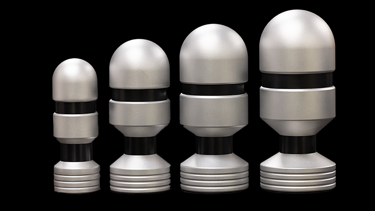
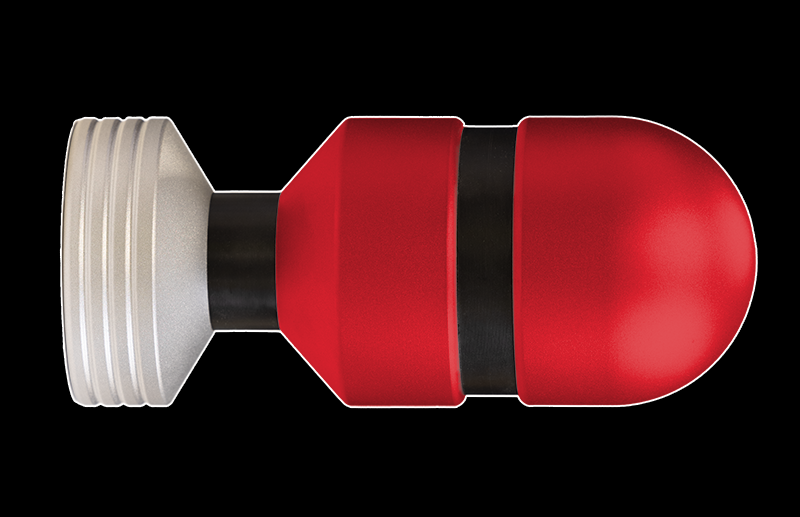
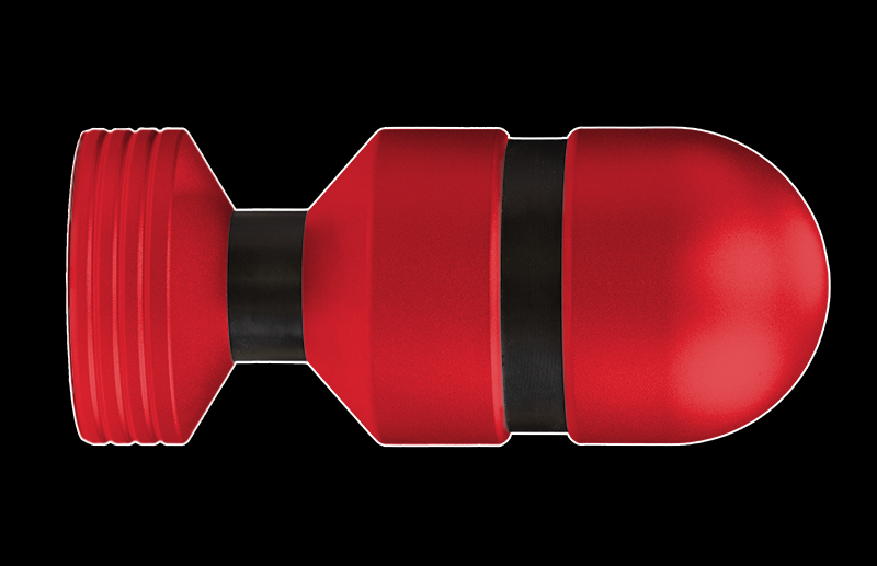
The E-Stim Systems Tripple electrodes are designed with not one, not two but 3 contact points giving far more sensation possibilities than a standard two pole BiPolar electrode.
CONNECTION AND CABLES
On the base of the electrode you will find three 4mm sockets, with dots beside each socket. The soccer with a single dot connects to the base, two dots connects to the middle contact point, and the socket with 3 dots connects to the head.
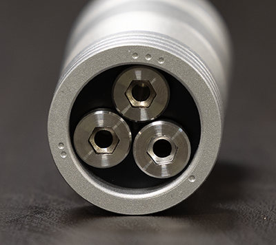
These are the connection sockets to your E-Stim Powerbox.
In order to connect your Tripple Electrode to an E-Stim Systems Powerbox you will need a 3.5mm to 4mm cable, or an E-Stim Systems TriPhase cable. To insert press each of the 4mm plugs gently into the relevant socket on the electrode, to remove twist the plug anti-clockwise, and gently pull the plug, not the cable. The single 3.5mm jack plug is designed to insert into the power box. Do not leave connecting plugs inserted into the electrode during storage.
TO USE
With a standard cable and a single channel you have several contact options Top/Base, Top/Mid, and Mid/Base, and of course if you are using an E-Stim systems power unit with asymmetrical biphasic outputs swapping the leads can result in a different sensation.
The connection sockets are marked with dots, a single dot for the base contact, two dots for the mid contact electrode and 3 dots for the Head contact.
Connection Options
Like all E-Stim Electrodes, we strongly suggest you experiment to find out what works for YOU and or your partner. But here re avfew ideas for you to start.
1 - 2 Base Mid
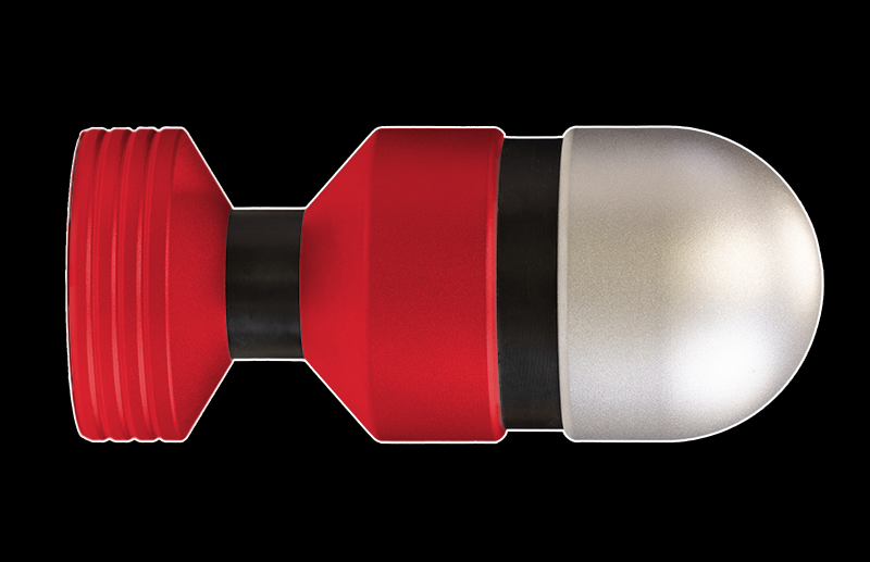
Base/Mid for a similar feel to our standard bipolar electrodes.
1-3 Base Head
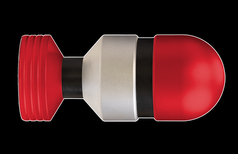
Base/Head for a wide experience over a larger area,
2-3 Mid Head - All the way in
Mid to Head for that deeper feeling, similar to that from our fully insertable electro eggs.
TriPhase - Everything
With a Triphase cable using all 3 sockets, and again choosing which sockets to plug in which plugs is a choice for you. but we always suggest experimenting and trying out new ideas to find out what works for you.
Finally if you don’t want to try the TriPhase but want Cock AND Insertable play then why not try base/mid (1-2) on one channel, and (3-cock) on the other.
Insertion
Connect the cable to the electrode, coat the electrode with conductive gel and then gently insert. The electrode is generally designed to be inserted up to the ‘neck’, with the base outside the body, and the head inside.
Once inserted, ensure the powerbox is switched off and the output level control is at minimum, then insert the 3.5mm jack plug into the correct socket.
NOTE: E-STIM ELECTRODES CANNOT BE USED WITH A CONDOM.
Switch the control box on and slowly increase the output level to provide the desired level of stimulation.
SAFETY WARNING
DO NOT CONNECT ANY ELECTRICAL DEVICE TO ANY LOCATION ABOVE THE WAIST (ACROSS THE ARMS COUNTS AS ABOVE THE WAIST!), BUT ESPECIALLY DO NOT CONNECT ACROSS THE HEART, CHEST, NECK OR HEAD. DO NOT USE IF YOUR SUBJECT IS FITTED WITH A PACEMAKER OR ARE PREGNANT.
Remember you use any e-stim device at your own risk. You must read and understand the user manual and all other instructions before attempting operation.
CLEANING
Always clean your electrode both before and after use and make sure the electrode is completely dry before storage.
Soap, hot water and medical grade cleaning wipes can be used to clean your electrode. Do NOT use caustic cleaning substances as this may damage the electrode.
Assembly / Disassembly
All E-Stim Systems Tripple electrodes, can be disassembled for cleaning.
When re-assembling ensure that the insulated sleeves in the base and the mid section contact are not forgotten as failure to fit them could result in the Electrode short circuiting and failing to operate correctly. Always ensure all socket bolts are tight before use.
Step 1
Using a 6mm Hex key start with the socket in the 3 dotted position (3) and loosen the bolt. This will loosen the Head Electrode and the Head Insulator
Now remove the Head Electrode, Head Insulator, and then the retaining bolt.
Step 2
There will be 2 plastic insulator sleeves in the hole on the Lower Head Electrode, these may come out with the bolt, or stay in the Lower Head Electrode, remove them but DO NOT loose the insulators.
Step 3
Using the same hex key, remove the bolt in the number 2 (two dots) position. This will allow you to remove the Lower Head Electrode, and the Neck Insulator, and then remove the retaining bolt.
Step 4
There will be two plastic insulator sleeves in the base holes, Remove these sleeves, but please DO NOT loose these sleeves, and do not muddle them up with the sleeves from the Lower Head Electrode, they might not be the same size.
Step 5
Lastly using the 6mm Hex Key, unscrew the last retaining bolt from the base. This will loosen the Insulator Plate. Remove the Insulator Plate.
Now you have all the parts separate you can clean the electrode. Do NOT use caustic cleaning substances as these will cause the electrode material to discolour.
If you loose any parts then spares are available, but missing parts are not covered by our lifetime guarantee.
To Assemble
Step 1
Push the insulator plate into the Base Electrode, with the locator stud innermost, and then insert the smallest bolt into the hole marked with a single Dot. Tighten the bolt loosely.
Step 2
Turn the Base Electrode over, exposing the 'neck' of the electrode and place the two base insulator sleeves into the two holes and then pass the middle length bolt in from the bottom, using the hole position marked with 2 dots.
Step 3
Slide the Neck Insulator onto the exposed bolt and align the holes. The Neck Insulator will have 2 holes, the Head Insulator will have only one. If you think the holes do not align up, then turn the neck insulator over and try again.
Step 4
Now align the Lower Head Electrode onto the exposed bolt, align the central locating pins and loosely tighten the bolt. The beveled side of the Lower Head Electrode faces the base.
Step 5
Now insert the Head Insulator Sleeves into the hole in the Lower Head Electrode, and then insert the remaining bolt into position 3 from the base. If you think the hole in the insulator does not align with the bolt, then remove the insulator and turn it over and try again.
Step 6
Place the Head Insulator onto the exposed bolt and the locating pin on the head insulator, then loosely screw in the bolt.
Finally
Now tighten the bolt in position 1, followed by the bolt in position 2, then lastly the bolt in position 3. Check all the sections are sitting flush and there are no major gaps or misalignments.
Your Tripple Electrode has now been re-assembled.
TO REMOVE
Switch off the control box and then unplug the cable from the Power Box.
Once the electrode is removed, clean it immediately. Make sure the electrode is completely dry before storage.
