Manuals

E-Stim Systems online Product Manuals
We are in the process of moving all of our manuals over to a digital web based format, with QR codes for easy access. This allows us to offer better accessibility for users with screen readers, as well as allowing online translation in various worldwide languages.
Power Box Manuals
2B (2.106 Firmware)
Electrode Manuals
Cock Play
ElectroRings , Stacker and the new Ring Racks
ElectroLoops (Conductive Rubber)
Insertables
Full List
Ring Racks
E-Stim Systems Ring Rack – User Guide
What is it?
The E-Stim Systems Ring Rack lets you connect multiple rings or Conductive Rubber Loops (with an adaptor) so they can be held and used all at the same time.
It comes in 4, 6, or 8 slot versions and has optional clip-in loop adaptors and even clip in 'teeth' if you want something with a little more bite.
Use it to stack up to eight contacts for creative multi-channel cock play.
Before You Start
- Make sure your power box is off.
- Gather your rings or loops and cables.
Setting It Up
- Choose the number of slots you need.
- Push each ring into a slot, line us the socket on the side, and the push a 4mm plug into the side hole and the ring. This should; d hold the ring securely
If you are planning to use conductive rubber loops, clip the loop adaptor in from the underside until it clips in, then threat the conductive rubber loop through and tighten with the loop lock on the top. The Clip in loop adaptors can work with both our 4mm and 2mm Loops.
You can use fewer than the total number of slots if you prefer.
Remember: at least two contact points are needed for current flow.
Connecting to Power
- Make sure your powerboat is TUIRNED OFF and the outputs set to ZERO
- Plug the Ring Rack leads into your e-stim power unit.
- Check that connections are tight and cables are safe.
Using the Ring Rack
- Position it as part of your setup.
- Turn your power unit on at the lowest setting.
- Increase slowly until you reach the desired level.
- Check comfort and stop immediately if you feel pain or burning. Using conductive gel will help to reduce hotspots.
- Limit session times to what feels comfortable.
Cleaning and Care
-
The Ring Rack is Made from 3D-printed biocompatible TPU. The Loop adaptors and Teeth are made from PLA.
-
Wash with mild soap and warm water or use an approved toy cleaner.
-
Do not boil, autoclave, or use alcohol or solvents.
-
Dry fully before storing.
-
Inspect before every use for cracks or damage.
Safety
- Always have two or more contact points connected.
- Never use near water or with people who have pacemakers.
- Stop use immediately if you feel discomfort or abnormal sensation.
Storage
-
Unplug from your power unit.
-
Remove the rings, unclip the adaptors and teeth. Clean and dry the Ring Rack.
-
Store it in a cool, dry place away from sharp objects or direct sunlight.
Troubleshooting
No sensation:
Check that at least two contacts are connected and cables are secure.
Uneven feeling:
Adjust spacing or check for dry skin and poor contact.
Visible damage:
Stop using and replace the damaged component.
Product Details
- Material: Biocompatible TPU
- Sizes: 4, 6, or 8 slot
- Colours: Red, Black, Yellow, Green, Blue
- Compatible with E-Stim Systems power units and electrode rings
For support or replacement parts, visit estim.store.
Holsters
Welcome
Congratulation on purchasing a new E-Stim Systems PowerBox Holster.
We all like to play with E-Stim, but sometimes it’s hard to find a way to keep the power box in place. So we took a few ideas and added in a bit of 3D print expertise and came up with our new powerbox holsters.
We currently have 2 styles, one created to fit the ElectroHelix, which also fits the ABox Mark 2, and the other design for the ElectroPebble, both work in the same way. The ElectroPebble version is slightly more curvy, and has a more open bottom clip. The Holster for the ElectroHelix and Box Mk2 has a solid bottom support clip.
The holsters are custom designed by us and then 3D printed in our own print farm. We are using TPU a biocompatible thermoplastic, the flexibility means it is easy to slot the power box in and retain them for normal play. The belt clip allows it to be clipped to a convenient belt or harness.
How to fit the PowerBox
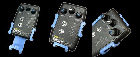
Hold the Holster and Slip the PowerBox in from the top, ensuring the arms fit around the PowerBox. The top retention clip of the holster should then clip in.
The arms are semi flexible, they are not designed to bend more than 45 degrees, doing so may break them - you have been warned
Attaching
The Holster is fitted with a belt clip on the rear. Simply slip it over any convene anent waistband, belt or harness.
Adjustment
The belt clips are also adjustable - just unscrew the screw in the belt clip and re position it in the desired position and then tighten the screws.
Cleaning
You can use hand hot soapy water to clean your holsters or medical grade cleaning solutions. do not use solvents. You cannot steam sterilise or boil the holsters.
PlugNuts
Coming Soon....
ElectroRing Size Set
Choosing the right size ElectroRing can be hard, so we have created a full set of sizing rings ,created so you can decide what size ring or rings you need.
How to Use
To use a set of e-stim sizing rings for the penis when fully erect, begin by ensuring you're in a private, relaxed setting. You do not need an e-stim device during this process, These rings are only for sizing, not for active use.
Run your finger around the inside of the sizing ring before use and check for any nicks or scratches.
Wait until your penis is fully erect. This is important because the ElectroRing ring needs to fit correctly during arousal, which is when e-stim is typically applied. Once erect, select a ring that looks like it might fit comfortably. Gently slide the ring down the shaft. It should go on with slight resistance but without any force or discomfort.
The right size should feel snug around the penis without causing pain, pressure, or a throbbing sensation. The ring should not be distorted. You should be able to wear it for a few minutes while erect, with no tingling, discolouration, or numbness. If any of these signs appear, remove the ring immediately and try a larger size.
If the ring feels too tight or difficult to remove, choose the next size up. If it slides on too easily or moves around, go down one size. Test a few nearby sizes until you find one that stays in place without cutting off circulation or causing discomfort.
Once you find the size that fits well during a full erection, write it down.
Only use the properly sized ring with your e-stim device, and follow all safety instructions included with the equipment.
After Use
The sizing rings are not designed for multiple uses, but if you wish to re use them, then clean all the rings thoroughly with warm water and mild soap, then dry them completely before storing. It is NOT possible to sterilise the rings.
Bi Polar ElectroWand Instructions
BELIEVE IN THE MAGIC
E-Stim Systems Bipolar electrodes are designed with both of the contact points needed for electroplay in the same insertable. The BiPolar Electrowands add in an extra element of an insulated handle allowing you greater control over the position of the electrode.
Given sufficient care your electrodes should last for years, and they are covered by our Lifetime Guarantee.
TO USE
Before you connect any cable to the powerbox, connect the cable to the electrode, there are 2 4mm sockets in the base of the handle, coat the electrode with conductive gel and then gently insert. The electrode is generally designed to be inserted up to the end of the ‘neck/handle join, but there are not issues if you with to insert further. The current will then flow between the head and base, stimulating the areas in-between.
Once the BiPolar ElectroWand is inserted, ensure the powerbox is switched off and the output level control is at minimum, then insert the 3.5mm jack plug into the correct socket on the powerbox.
NOTE: E-STIM ELECTRODES CANNOT BE USED WITH A CONDOM.
Switch the control box on and slowly increase the output level to provide the desired level of stimulation. For a slightly different effect you can swap the 4mm plugs over.
If you remove the ElectroWand while it is still powered the intensity of sensation may increase.
The ElectroWand can also be used on the surface of the skin, simply use a small about of conductive gel on the skin to
SAFETY WARNING
DO NOT CONNECT ANY ELECTRICAL DEVICE TO ANY LOCATION ABOVE THE WAIST (ACROSS THE ARMS COUNTS AS ABOVE THE WAIST!), BUT ESPECIALLY DO NOT CONNECT ACROSS THE HEART, CHEST, NECK OR HEAD. DO NOT USE IF YOUR SUBJECT IS FITTED WITH A PACEMAKER OR ARE PREGNANT.
Remember you use any e-stim device at your own risk. You must read and understand the user manual and all other instructions before attempting operation.
CLEANING
Always clean your electrode both before and after use and make sure the electrode is completely dry before storage.
Soap, hot water and medical grade cleaning wipes can be used to clean your electrode. Do NOT use caustic cleaning substances as this may damage the electrode.
The BiPolar ElectroWands can be disassembled for cleaning. When re-assembling ensure that the insulated plate is correctly inserted onto the mounting bolt and the mounting bolt has the insulated bush fitted facing inwards. If you inadvertently loose a piece, spares are available.
CONNECTION AND CABLES
On the base of the ElectroWand you will find two 4mm holes. These are the connection sockets to your powerbox.
In order to connect your electrode to an E-Stim Systems Powerbox you will need a 3.5mm to 4mm cable. To insert press each of the 4mm plugs gently into the relevant socket on the electrode, to remove twist the plug anti-clockwise, and gently pull the plug, not the cable. The single 3.5mm jack plug is designed to insert into the power box. Do not leave connecting plugs inserted into the electrode during storage.
TO REMOVE
Switch off the control box and then unplug the cable from the Power Box.
Once the electrode is removed, clean it immediately. Make sure the electrode is completely dry before storage.
Tripples
Tripple Instructions
DESIGNED FOR PLEASURE
The new E-Stim Systems Tripple electrodes are designed with not one, not two but 3 contact points giving far more sensation possibilities than a standard two pole BiPolar electrode.
<family pic>
CONNECTION AND CABLES
On the base of the electrode you will find three 4mm sockets, with dots beside each socket. The soccer with a single dot connects to the base, two dots connects to the middle contact point, and the socket with 3 dots connects to the head.
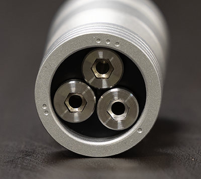
These are the connection sockets to your E-Stim Powerbox.
In order to connect your Tripple Electrode to an E-Stim Systems Powerbox you will need a 3.5mm to 4mm cable, or an E-Stim Systems TriPhase cable. To insert press each of the 4mm plugs gently into the relevant socket on the electrode, to remove twist the plug anti-clockwise, and gently pull the plug, not the cable. The single 3.5mm jack plug is designed to insert into the power box. Do not leave connecting plugs inserted into the electrode during storage.
TO USE
With a standard cable and a single channel you have several contact options Top/Base, Top/Mid, and Mid/Base, and of course if you are using an E-Stim systems power unit with asymmetrical biphasic outputs swapping the leads can result in a different sensation.
The connection sockets are marked with dots, a single dot for the base contact, two dots for the mid contact electrode and 3 dots for the Head contact.
Connection Options
Like all E-Stim Electrodes, we strongly suggest you experiment to find out what works for YOU and or your partner. But here re avfew ideas for you to start.
1 - 2 Base Mid
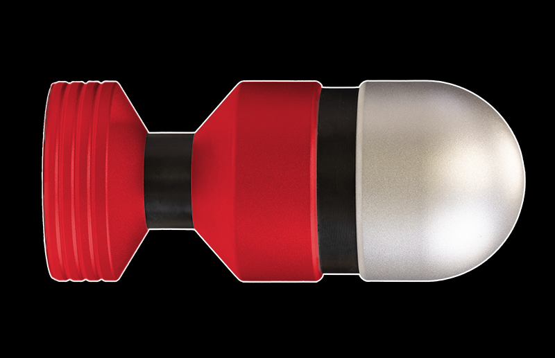
Base/Mid for a similar feel to our standard bipolar electrodes.
1-3 Base Head
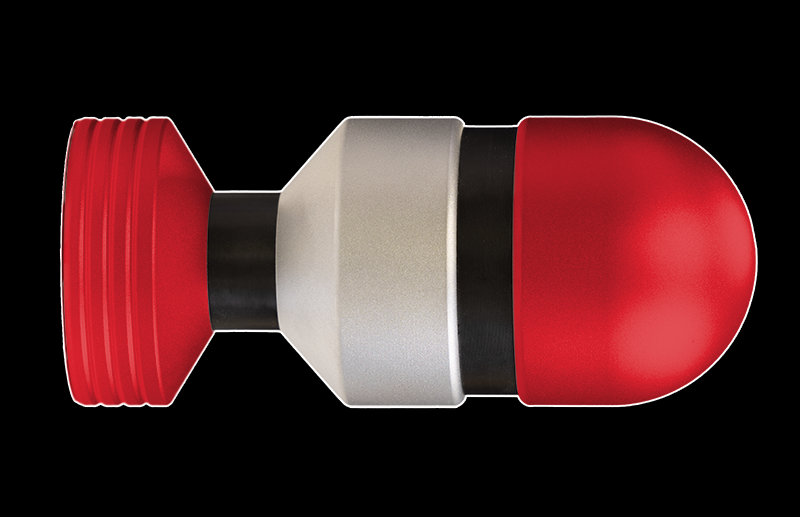
Base/Head for a wide experience over a larger area,
2-3 Mid Head - All the way in
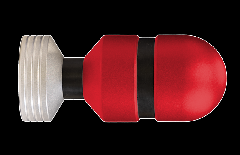
Mid to Head for that deeper feeling, similar to that from our fully insertable electro eggs.
TriPhase - Everything
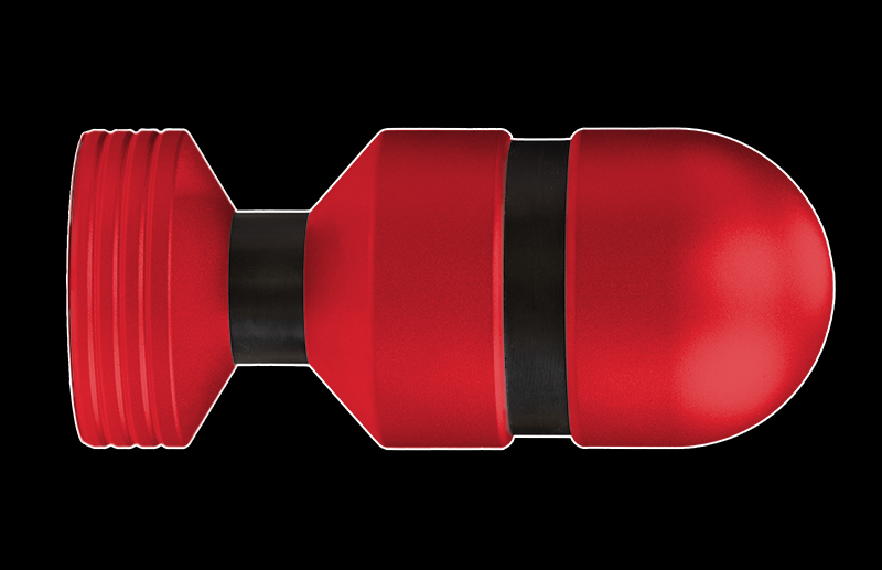
With a Triphase cable using all 3 sockets, and again choosing which sockets to plug in which plugs is a choice for you. but we always suggest experimenting and trying out new ideas to find out what works for you.
Finally if you don’t want to try the TriPhase but want Cock AND Insertable play then why not try base/mid (1-2) on one channel, and (3-cock) on the other.
Insertion
Connect the cable to the electrode, coat the electrode with conductive gel and then gently insert. The electrode is generally designed to be inserted up to the ‘neck’, with the base outside the body, and the head inside.
Once inserted, ensure the powerbox is switched off and the output level control is at minimum, then insert the 3.5mm jack plug into the correct socket.
NOTE: E-STIM ELECTRODES CANNOT BE USED WITH A CONDOM.
Switch the control box on and slowly increase the output level to provide the desired level of stimulation.
SAFETY WARNING
DO NOT CONNECT ANY ELECTRICAL DEVICE TO ANY LOCATION ABOVE THE WAIST (ACROSS THE ARMS COUNTS AS ABOVE THE WAIST!), BUT ESPECIALLY DO NOT CONNECT ACROSS THE HEART, CHEST, NECK OR HEAD. DO NOT USE IF YOUR SUBJECT IS FITTED WITH A PACEMAKER OR ARE PREGNANT.
Remember you use any e-stim device at your own risk. You must read and understand the user manual and all other instructions before attempting operation.
CLEANING
Always clean your electrode both before and after use and make sure the electrode is completely dry before storage.
Soap, hot water and medical grade cleaning wipes can be used to clean your electrode. Do NOT use caustic cleaning substances as this may damage the electrode.
Assembly / Disassembly
All E-Stim Systems Tripple electrodes, can be disassembled for cleaning.
When re-assembling ensure that the insulated sleeves in the base and the mid section contact are not forgotten as failure to fit them could result in the Electrode short circuiting and failing to operate correctly. Always ensure all socket bolts are tight before use.
Step 1
Using a 6mm Hex key start with the socket in the 3 dotted position (3) and loosen the bolt. This will loosen the Head Electrode and the Head Insulator
Now remove the Head Electrode, Head Insulator, and then the retaining bolt.
Step 2
There will be 2 plastic insulator sleeves in the hole on the Lower Head Electrode, these may come out with the bolt, or stay in the Lower Head Electrode, remove them but DO NOT loose the insulators.
Step 3
Using the same hex key, remove the bolt in the number 2 (two dots) position. This will allow you to remove the Lower Head Electrode, and the Neck Insulator, and then remove the retaining bolt.
Step 4
There will be two plastic insulator sleeves in the base holes, Remove these sleeves, but please DO NOT loose these sleeves, and do not muddle them up with the sleeves from the Lower Head Electrode, they might not be the same size.
Step 5
Lastly using the 6mm Hex Key, unscrew the last retaining bolt from the base. This will loosen the Insulator Plate. Remove the Insulator Plate.
Now you have all the parts separate you can clean the electrode. Do NOT use caustic cleaning substances as these will cause the electrode material to discolour.
If you loose any parts then spares are available, but missing parts are not covered by our lifetime guarantee.
To Assemble
Step 1
Push the insulator plate into the Base Electrode, with the locator stud innermost, and then insert the smallest bolt into the hole marked with a single Dot. Tighten the bolt loosely.
Step 2
Turn the Base Electrode over, exposing the 'neck' of the electrode and place the two base insulator sleeves into the two holes and then pass the middle length bolt in from the bottom, using the hole position marked with 2 dots.
Step 3
Slide the Neck Insulator onto the exposed bolt and align the holes. The Neck Insulator will have 2 holes, the Head Insulator will have only one. If you think the holes do not align up, then turn the neck insulator over and try again.
Step 4
Now align the Lower Head Electrode onto the exposed bolt, align the central locating pins and loosely tighten the bolt. The beveled side of the Lower Head Electrode faces the base.
Step 5
Now insert the Head Insulator Sleeves into the hole in the Lower Head Electrode, and then insert the remaining bolt into position 3 from the base. If you think the hole in the insulator does not align with the bolt, then remove the insulator and turn it over and try again.
Step 6
Place the Head Insulator onto the exposed bolt and the locating pin on the head insulator, then loosely screw in the bolt.
Finally
Now tighten the bolt in position 1, followed by the bolt in position 2, then lastly the bolt in position 3. Check all the sections are sitting flush and there are no major gaps or misalignments.
Your Tripple Electrode has now been re-assembled.
TO REMOVE
Switch off the control box and then unplug the cable from the Power Box.
Once the electrode is removed, clean it immediately. Make sure the electrode is completely dry before storage.
Video
ElectroRing System Stacker
What is it?
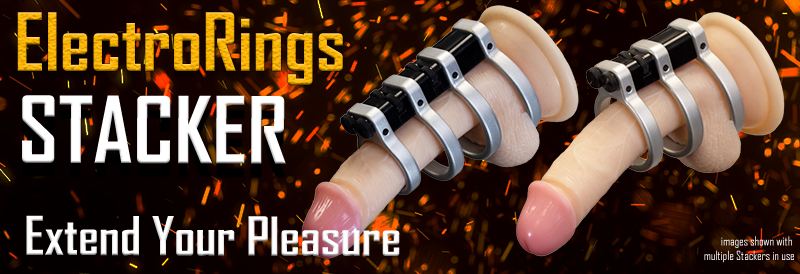
The Stacker. A tiny little magical block that extents the use of the ElectroRing System. Each Stacker allows you to add an extra ElectroRing, but still maintains the electrical isolation, giving you more points of contact to choose from.
How to Use
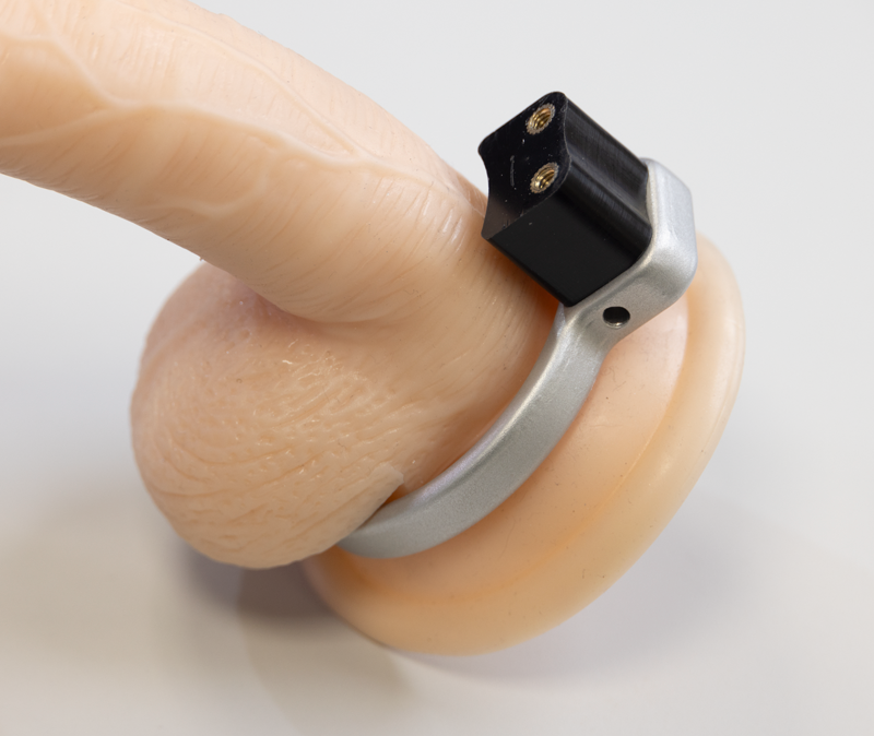 Assemble the ElectroRing System as usual, with a Larger ElectroRing and the standard (or extended) spacer block.
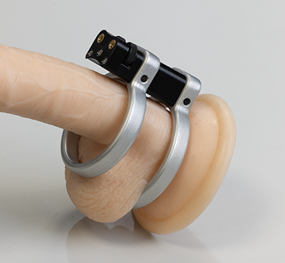 Now instead of using the two knurled screws used to normally secure the front ring, Add an ElectroRing and the Stacker Block.
Align the exposed screws with the holes in the ElectroRing, and rotate each knurled knob in the Stacker around 1/2-1 turns, Turn one knob then the other to tighten the stacker down on to the ElectroRing.
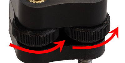
If you turn the knobs too much, or you try to tighten one knob more than the other then you can jam the Stacker, if this occurs just turn the knobs in the opposite direction to release the tension.
Once the Stacker is holding the ElectroRing, position the next ElectroRing on the top of the Stacker, and use the normal knurled screws to attach. If you want to add more ElectroRings, then add a second Stacker instead.
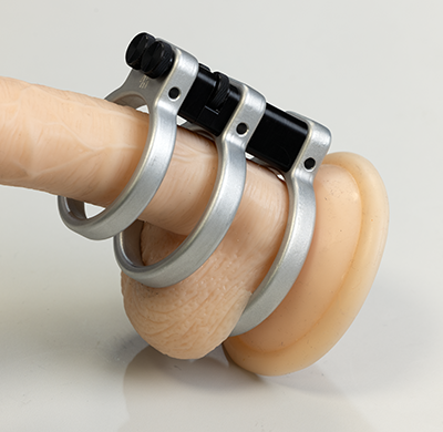
Multiple Stackers can be used, one Stacker is required for each additional ElectroRing used.
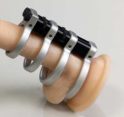
Multiple ElectroRings and Stackers will create a structure that will flex slightly. Do not put abnormal pressure on the stacker blocks as they may break if forced.
It is not possible to stack stackers without using a ElectroRing, and the last or ‘front ElectroRing’ will need to be secured with the two standard screws from the Accessory Pack.
How to Disassemble
To Disassemble the ElectroRings and the Stacker(s), Simply reverse the assembly process.
To Clean
It is possible to disassemble the Stacker for cleaning.
Remove from any ElectroRing and unscrew the 3 cross head screws. No NOT loose them!!
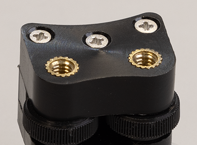
The top and bottom sections can then be separated and the knurled screws removed.
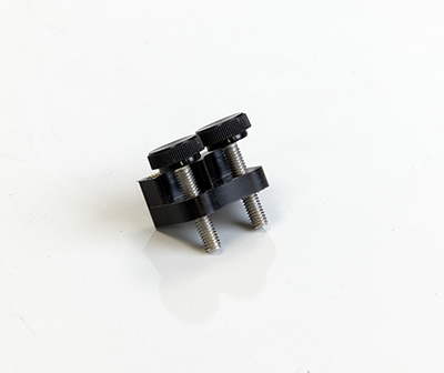
The separated parts can now be cleaned.
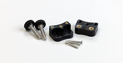
Note the knurled screws in the Stacker are longer than those supplied in the standard ElectroRing Accessory Pack - do not get them confused, the standard ElectroRing Accessory Pack retention screws will not work in the Stacker.
Re assembly is a reverse of the disassembly process. Insert the two knurled screws into the shouldered base plate with the 3 brass coloured inserts uppermost, place the top plate (the plate with the two brass inserts) uppermost, on top and then screw together with the 3 cross head screws.
Conductive Rubber Loops
Congratulations on your purchase of a pair of E-Stim Systems Conductive Rubber Loops. These conductive rubber loops offer a comfortable and safe introduction to electro play, and are available in 2mm and 4mm Versions.
Adjustments
The conductive rubber loops are supplied with a spring loaded adjustable collar. Simply squeeze the collar to release the tension on the rubber loop, then adjust the size of the loop. Release the collar when you are happy with the fit.
Be careful when pulling on the rubber loops they will snap if excessive force is used. Try not to remove the collar completely as it is possibly to loose the small spring.
Safety
DO NOT CONNECT ANY ELECTRICAL DEVICE TO ANY LOCATION ABOVE THE WAIST. DO NOT CONNECT ACROSS THE HEART, CHEST, NECK OR HEAD. DO NOT USE IF FITTED WITH A PACEMAKER OR IF YOU ARE PREGNANT. REMEMBER YOU USE THIS DEVICE AT YOUR OWN RISK.
Cleaning
The conductive loops may be cleaned with soap and water, medical grade cleaning wipes or other cleaning materials suitable for medical instruments. Ensure the loops are clean and dry before storage.
Connection
Each conductive loop has two holes in the end of the rubber. To connect, simply push a plug of the relevant size into one loop, and the other plug into a hole on the other loop. (Not on the same loop). To remove pull the plug (not the wire) and gently twist anticlockwise. A small dab of water based lube may aid insertion and extraction.
Testing
If you are unsure as to the effect the conductive loops might have, then try them on your hand first. Ensure the loops do not touch each other.
To use
Place the loops on the penis ensuring they do not touch each other, and adjust the size so they are comfortable. Connect one plug to one loop and the other to the other loop, (as noted previously). In use the current will then flow between the two loops, stimulating the areas in-between.
Switch the control box on and slowly increase the output level to provide the desired level of stimulation.
If the subject feels discomfort then reduce the power levels.
To remove
Reduce the output levels to minimum, switch off the box and then unplug the cable from the control box. Do not remove the cables from either the control unit or the electrode whilst in operation as inadvertent electric shocks may be experienced.
UltraSounds
Welcome to the UltraSounds.
Monopole electrodes such as UltraSounds are designed for use with a second point of contact. This can be either a surface electrode such as a sticky pad, conductive rubber loop or cock strap, or another insertable electrode.
Safety
DO NOT CONNECT ANY ELECTRICAL DEVICE TO ANYLOCATION ABOVE THE WAIST (ACROSS THE ARMSCOUNTS AS ABOVE THE WAIST!), BUT ESPECIALLYDO NOT CONNECT ACROSS THE HEART, CHEST,NECK OR HEAD. DO NOT USE IF FITTED WITH APACEMAKER OR ARE PREGNANT. REMEMBER YOUUSE THIS DEVICE AT YOUR OWN RISK.
Cleaning
Always clean your UltraSound both before and after use. Ensure that it is dry before storage. Soap, hot water and medical grade cleaning wipes such as our Disinfectant Wipes can be used to clean your UltraSound. It can also be boiled in water to sterilise them. Do NOT use caustic cleaning substances as this may damage the UltraSound.
Before Use
Always inspect the UltraSound thoroughly before use for nicks and scratches or any other damage. If it is found to be damaged then DO NOT USE. Using a damaged UltraSound could result in an injury.
Connection
On the base of the UltraSound you will find a single 4mm socket. To use the UltraSound you will need either a 4mmConnection Cable or Bi-Cable together with an additional electrode/point of contact otherwise the UltraSound will not work.
Use
The following is guidance based on a users experience and should not be considered expert instruction. If you are unsure about any of the practicalities of Urethral play, then we suggest you seek expert advice before play. If you feel any sharp pain or more than mild discomfort at any point then you stop straightaway.
Ensure the UltraSound is cleaned both before and after use, Connect the UltraSound to the 4mm cable. Prepare the UltraSound for use by coating it and the opening of the urethra with a sterile lubricant. It is very important that there is enough lubricant otherwise insertion can be painful. It is easier to begin to insert the UltraSound if you are semi erect and lying down on your back.
Gently place the rounded tip of the UltraSound into the entrance of the urethra; you may have to use a little pressure initially just to get things moving but be gentle. Once the UltraSound is partially in you will feel it gently slip down the shaft and then stop. Let the weight of the UltraSound do the work, do not force it.
Now begin to slowly point your penis towards your toes and you will find the UltraSound drops in a little more. This movement allows you to straighten out the kinks in the urethra and give a straight path for the UltraSound to follow. Once again let the weight of the UltraSound do the work. It will come to another stop and if you bring your penis back towards your belly button the rest should slip in gently.
If you do not wish for deep urethral play then only follow the initial stages. It is imperative that if you feel any sharp pain or more than mild discomfort you stop straight away. Keep the Urethra well lubricated at all times. It is advised that you only begin stimming once the UltraSound is in a comfortable position.
Once connected, switch the power box on and slowly increase the power until the desired stimulation is achieved. The UltraSound is designed to be inserted into the penis and can be gently moved in and out of the urethra to create a pleasurable sensation. To do this hold the 4mmplug and not the end of the UltraSound as otherwise you will feel a tingle through your fingers.
If at any time you wish to stop play turn the output setting down and switch the box off first. Do NOT remove the cables from either the box or the electrode whilst in operation as inadvertent shocks may be experienced.
To Remove
Reduce the output levels to minimum, switch off the control box and then unplug the cable from the control unit. Slowly and gently remove the UltraSound from the urethra. Once removed clean it immediately ensuring it is completely dry before storage. It is also advisable to urinate soon after to flush any lube from the urethra.
To remove the plug from the socket in the UltraSound gently pull the plug (not the wire) and twist anticlockwise .
Do not leave the connecting plugs inserted into the electrode during storage or cleaning.
ElectroRings System
 Welcome
Welcome to the new E-Stim Systems ElectroRing System.
Others may offer simple cock rings, we have created not just a single ElectroRing but a system that can function not only as cock rings but can also take your electro cock play experience to the next dimension with a more chastity like device, even to the extend of not being able to remove the ElectroRing System without tools.
Each ElectroRing has been created to work with our heavy duty 4mm connectors, perfectly designed for use with our low profile cables. We don't even force you to choose which side you connect the cable to - the socket connections are double sided.
You can use the E-Stim ElectroRings either as a single ring or as part of a Bipolar System. You can even add more ElectroRings with the new ElectroRing Stacker.
Safety
DO NOT CONNECT ANY ELECTRICAL DEVICE TO ANY LOCATION ABOVE THE WAIST (ACROSS THE ARMS COUNTS AS ABOVE THE WAIST!), BUT ESPECIALLY DO NOT CONNECT ACROSS THE HEART, CHEST, NECK OR HEAD. DO NOT USE IF FITTED WITH A PACEMAKER ARE EPILEPTIC OR ARE OR MAYBE PREGNANT. REMEMBER YOU USE THIS DEVICE AT YOUR OWN RISK.
The ElectroRing System
The E-Stim Systems ElectroRing System is a bipolar set of rings separated from each other with an insulator giving bipolar sensations. Generally you have a larger ring behind the testicles and a smaller Ring 'locked' onto the penile shaft with two thumb screws, the Ring System is easy to use and highly effective. You can add multiple ElectroRings with a Stacker, one Stacker will be required for each ElectroRing.
If you find the insulator block is too small, we also offer a longer 30mm insulator block.
Secure as you wish
If you want it more secure then use the Hex headed bolts instead of the Thumb screws, - that way your subject will find it highly difficult to remove without the correct tool.

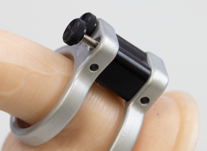
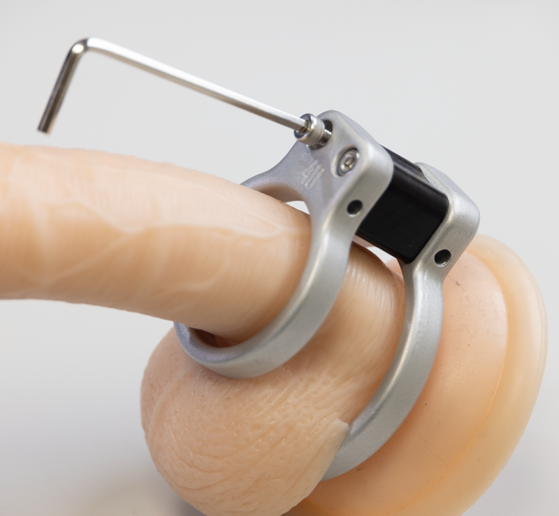
How to fit the original ElectroRing System
- Using the supplied hex key screw the insulator block to the larger ring. Make sure the screw heads fit into the recesses in the ring. Do not over tighten. This is the ring that will fit behind the testicles.
- Now place the ring over the shaft and testicles and slip the testicles in one at a time, so the ring now sits at the base of the shaft.
- Slide the second ring over the shaft, align the screw holes on the ring with the insulator block and then screw in the black headed screws. Do not over tighten and be careful not to trap any delicate skin when screwing it all together. If you are looking for something a little more secure, that will required a tool to remove, then use the smaller Allen headed screws.
- Using an E-Stim Systems 4mm connection cable insert one plug into one ring, and the other plug on the other ring. DO NOT plug both plugs into the same ring.
- Plug into your power box, don't forget to ensure the box is switched off.
- Lastly, Make sure the levels are at zero and then switch your power box on. Gradually turn the levels up and enjoy!!!
If you experience sharpness or hotspots then consider using conductive gel to lubricate and smooth the sensation.
To Remove
- Turn the outputs of the power box to zero, Switch the power box off and unplug the power cable.
- Unscrew the black headed screws, or if you are using the more secure bolts, use the supplied hex key.
- Slide off the front ring.
- Lastly manoeuvre the testicles and shaft through the larger ring.
Using Single Rings
You can if you wish use a single ring as a more conventual cock ring, on in conjunction with another electrode as a second point of contact. In this situation all you need to do is to slip the ring on in the position you wish, and connect to an E-Stim Systems power box with a connection cable with a 4mm plug. If you are using a single ring, then ensure it does not touch anything else that is part of the circuit, or a short circuit may occur.
DO NOT connect two plugs into the same ElectroRing.
Cleaning
As with all of our insertable electrodes clean before and after use. Do not use caustic cleaning solutions, and always ensure the ElectroRings System and all the component parts are dry before storing. Use of bleach may cause the ElectroRings to discolour and is not recommended.
Lifetime Guarantee
The ElectroRing and ElectroRing System is covered by our lifetime guarantee. If it fails in normal use then we will repair or replace items free of charge. This does not include the cost of shipping, nor does it cover items that are 'lost'. In addition, we cannot and will not accept returns if you simply get your sizing wrong.
Want more information?
We talk about the ins and outs of the ElectroRing system
Penis Plug
 Congratulations on your purchase of an E-Stim Systems PenisPlug™. (Otherwise known as a PenisPlug)
Monopole electrodes such as the PenisPlug are designed for use with a second point of contact. This can be either a surface electrode such as a sticky pad, conductive rubber loop or cock strap, or another insertable electrode.
Safety
DO NOT CONNECT ANY ELECTRICAL DEVICE TO ANY LOCATION ABOVE THE WAIST (ACROSS THE ARMS COUNTS AS ABOVE THE WAIST!), BUT ESPECIALLY DO NOT CONNECT ACROSS THE HEART, CHEST, NECK OR HEAD. DO NOT USE IF FITTED WITH A PACEMAKER ARE EPILEPTIC OR ARE OR MAYBE PREGNANT. REMEMBER YOU USE THIS DEVICE AT YOUR OWN RISK.
Cleaning
Always clean your PenisPlug both before and after use. Ensure theat it is dry before storage. Soap, hot water and medical grade cleaning wipes such as our Disinfectant Wipes can be used to clean your PenisPlug. It can also be boiled in water to sterilise them, (although they may discolour). Do NOT use caustic cleaning substances as this may damage the PenisPlug.
Check Before use
Always inspect the PenisPlug thoroughly before use for nicks and scratches or any other damage. If it is found to be damaged then DO NOT USE. Using a damaged Penis Plug could result in an injury.
Connection
On the base of the PenisPlug you will find a single 4mm socket. To use the PenisPlug you will need an E-Stim Systems 4mm Connection Cable, or an E-Stim Systems Low Profile Cable or an E-Stim Systems BiCable together with an additional electrode or point of contact otherwise the PenisPlug will not work.
Use
The following is guidance based on a users experience and should not be considered expert instruction. If you are unsure about any of the practicalities of Urethral play, then we suggest you seek expert advice before play. If you feel any sharp pain or more than mild discomfort at any point you stop straight away.
Ensure the Penis Plug is cleaned both before and after use as previously described and connect the Penis Plug to the cable. Prepare the Penis Plug for use by coating it and the opening of the Urethra with a Sterile Lubricant. It is very important that there is enough lubricant otherwise insertion can be painful. It is easier to begin to insert the Penis Plug if you are semi erect.
Gently place the rounded tip of the PenisPlug into the entrance of the Urethra; you may have to use a little pressure initially just to get things moving but be gentle. The Urethra will need to stretch enough to allow the head of the PenisPlug to slip in, take time to allow this to happen and do not force it in. Once the PenisPlug is in far enough for the bulb to be fully within the Urethra you may feel it gently slip down the shaft as the Urethra closes behind the bulb. If this does not happen consider gently removing the Penis Plug and applying more Sterile Lube and try again.
The Urethra is a delicate part of the body and so be gentle and take your time to insert the PenisPlug. The PenisPlug can be inserted all the way up to the base, and having the base in contact with the head of the penis can generate some great sensations.
It is imperative that if you feel any sharp pain or more than mild discomfort you stop straight away. Keep the Urethra well lubricated at all times. It is advised that you only begin stimming once the Penis Plug is in a comfortable position.
Once connected, switch the power box on and slowly increase the power until the desired stimulation is achieved. The PenisPlug is designed to be inserted into the penis and can be gently moved in and out of the Urethra to create a pleasurable sensation. To do this hold the 4mm plug and not the end of the PenisPlug as otherwise you may feel a tingle through your fingers.
If at any time you wish to stop play turn the output setting down and switch the box off first. Do NOT remove the cables from either the box or the electrode whilst in operation as inadvertent shocks may be experienced.
To remove
Reduce the output levels to minimum, switch off the control box and then unplug the cable from the control unit. Slowly and gently remove the PenisPlug from the Urethra. Remembering that unlike with a sound the Urethra needs to expand again to allow the PenisPlug to be removed, so again take your time and be gentle. Once removed clean it immediately ensuring it is completely dry before storage. It is also advisable to urinate soon after to flush any lube from the Urethra.
To remove the plug from the socket in the PenisPlug gently pull the plug (not the wire) and twist anticlockwise .
Do not leave the connecting plugs inserted into the electrode during storage or cleaning.
The ABox (Mk2)

Congratulations on purchasing an E-Stim Systems ABox™ Mk2. Given sufficient care your new unit should give you many years of erotic sound driven electro stimulated pleasure. Before starting always read the instructions and ensure you are completely familiar with all of the controls and the safety warnings prior to use.
Key Features
- More power and range than our original Classic ABox.
- Sound driven E-Stim with a built in adjustable sensitivity microphone.
- Stereo Input, with a built in mixer – able to cope with a variety of input sources, both mono and stereo.
- Built in input level display.
- Simple stepless control of maximum output level.
- Switched mode voltage generation… no bulky transformers.
- Hours of fun from a single PP3 battery.
- Single channel output allows the use of unipolar and bipolar electrodes.
- Current limited AC output to ensure complete safety and avoid the possibility of electrode polarisation.
|
SAFETY WARNING (DO NOT CONNECT THE E-Stim Systems ABox Mk2™ OR ANY ELECTRICAL DEVICE TO ANY LOCATION ABOVE THE WAIST (ACROSS THE ARMS COUNTS AS ABOVE THE WAIST!), BUT ESPECIALLY DO NOT CONNECT ACROSS THE HEART, CHEST, NECK OR HEAD. DO NOT USE IF FITTED WITH A PACEMAKER OR ARE PREGNANT. REMEMBER YOU USE THIS DEVICE AT YOUR OWN RISK. YOU MUST READ AND UNDERSTAND THE USER MANUAL AND ALL OTHER INSTRUCTIONS BEFORE ATTEMPTING OPERATION. |
What is the ABox Mk2™?
A Classic improved.
Back in 2006 we created the original ABox, the worlds first commercial E-Stim unit that just ran off a sound source. Its been highly popular since it's launch and in 2020 we decided to give it a little more. The ABox Mk2, is the result. With a smaller case (the same size as our ElectroHelix), more power and improved audio response, the Mk2 has already show its a worthy successor.
Designed for audio pleasure
The ABox Mk2™ is designed specifically for Erotic Audio Driven Electro Stimulation. Rather than just being sound triggered, the E-Stim Systems ABox Mk2™ is sound driven. The input, whether from the built in microphone or the stereo input, is converted to a powerful Electro-Stim sensation. Picking up sound from either a linked source such as a Computer, MP3 device or even the ambient atmosphere via the built in microphone results in an E-Stim experience that has been described by some as ‘out of this world’.
More than StereoStim
The ABox Mk2 is NOT a simple stereo stim unit. The original classic ABox, and now the new ABox Mk2 have been created to work with normal audio sources to provide an in depth, intense and enjoyable E-Stim experience, an experience that is more effective and nuanced when used with complex audio sources, like the human voice and music.
Using standard mono tonal tracks of screeches and whistles common with stereo stim devices will not demonstrate the power and pleasure of combining aural pleasure of music with e-stim sensations, so forget the single tones and individual discreet frequencies, plug in your favourite musicians and enjoy feeling the music as well as listening to it!! Why did we do it this way? We like to be different!!!
Voice Control
Learn to drive your subject wild with just the power of your voice. The ability to change the nature of the output just by changing the level and tonal qualities of your voice is a powerful addition to any game. The old adage ‘Silence in Golden’ brings a new meaning when the ABox Mk2™ is used in a BDSM dungeon environment.
Experiment
The only way to get the best out of your ABox Mk2™ is to experiment. BDSM players can spend hours with the microphone input, putting new meaning to the demand for silence, whilst using the ABox Mk2™ in a Dance or Club environment can drive anyone wild. Coupled with a MP3 player (obviously not supplied) and suitable music, the range of sensations that the ABox Mk2™ can generate can be mind blowing.
Fitting a battery

- Ensure the unit is switched off, and any electrode connection jacks are disconnected.
- Turning the unit over and using your thumb press and slide the battery compartment lid towards the bottom of the unit.
- Remove the old battery (if fitted) and replace with a fresh Alkaline PP3. The battery connector is polarized so it should not be possible to connect the battery incorrectly, but ensure the polarity is correct before attempting connection.
- Place the battery into the unit and replace the battery compartment cover. The cover is fitted with two tabs which insert into the lower half of the case first, then slide the top half of the cover which will then click into position.
- Turn the unit over. The unit is now ready for operation.
Please note we do NOT recommend the use of standard re-chargeable batteries in the E-Stim ABox™ unit NiMh re-chargeable, with a terminal voltage of 8.4V or above may be used with a possible reduction in output power.
In the event the ABox™ is not being used for a period of time, remove the battery.
Testing
Testing the microphone input.
Ensure the unit is switched off, then fit a battery.
Set the Output Level Control and Microphone Sensitivity to minimum. Slide the input selector switch to the right to select ‘mic’.![]()
Switch the unit on, by sliding the power switch to the right.![]() The power on LED should illuminate. Wait a few seconds for the unit to charge.
The power on LED should illuminate. Wait a few seconds for the unit to charge.
Speak with a normal voice at a distance of around 30cm (12”) and gradually turn the Microphone Sensitivity control up. The level display LEDs should begin to flash in time with you voice. Adjusting the microphone sensitivity using the control will allow you to cater for various ambient sound conditions.
Battery Low Condition
If the first 25% LED glows continuously when there is no sound input present, then this is an indication that the battery voltage is low. A low battery will result in lower output levels, together with reduced microphone sensitivity.
Testing Stereo input
Using the supplied stereo connection cable connect the headphone out of your audio device to the input of the ABox Mk2™. ENSURE YOU DO NOT CONNECT THE INPUT TO THE OUTPUT SOCKET. Such an action, due to the high output voltages present could destroy your ABox Mk2™ and any other device connected to it. Damage caused by inadvertent connection of the output sockets to anything other than E-Stim Electrodes will invalidate your lifetime guarantee.
Adjust the volume control of the audio device to ensure the input level as indicated by the display is just flashing the 100% LED. This will provide maximum tonal range.
Frequency Response
Because the human body does not respond to E-Stim Signals above 6Khz, audio signals with a substantial high frequency component may not always produce the result that you would expect. For the same reason low frequency signals below 30Hz will be poor sources for stimulation.
The ABox is not designed to work with monotone sources typical with home made stereostim devices. This does not mean they will not work, just the ABox was not designed predominantly to work with such sources. The ABox is designed to give a sensation from more complex sound sources such as the voice and music. Like music in general not all sound sources are going to give you a sensation that you will feel or enjoy. The key is to experiment and to find material that YOU enjoy.
Ideal Levels
The ideal input level in both the microphone and stereo input modes should result in the maximum input LED flashing from time to time indicating a peak. A signal that results in the 100% LED being illuminated continuously will cause distortion and not allow the full output range to be utilized.
Using the ABox Mk2™
Turn the unit off, set the output level control to minimum and connect a suitable electrode via one of the output jacks. Connect an electrode to a suitable section of the body. (DO NOT CONNECT THE E-Stim Systems ABox Mk2™ UNIT OR ANY ELECTRICAL DEVICE TO ANY LOCATION ABOVE THE WAIST (ACROSS THE ARMS COUNTS AS ABOVE THE WAIST!), BUT ESPECIALLY DO NOT CONNECT ACROSS THE HEART, CHEST, NECK OR HEAD. DO NOT USE IF FITTED WITH A PACEMAKER OR ARE PREGNANT. REMEMBER YOU USE THIS DEVICE AT YOUR OWN RISK.
Turn the unit on and slowly turn the output level control up. You should begin to feel a slight tingling sensation from the electrode site.
If you or your subject experiences any pain or discomfort then stop using immediately. If necessary use lubrication as any E-Stim device is potentially capable of causing burning when used on sensitive and or small contact areas at high output levels.
Experiment! Only with experience with you get the most out of your Mk2 ABox™. You will find that different modes and levels will give different sensations.
Always bear in mind the safety warnings.
Internal Microphone
The internal microphone is mounted internally, facing up, between the control knobs, and depending on the setting of the microphone sensitivity control knob, it is sensitive enough to pick up speech and music. The internal microphone is also sensitive to taps and knocks on the case of the unit itself.
Caution
Always ensure the unit is switched off and all controls are set to minimum before connecting to any other device. Always ensure all connections are secure and free from corrosion.
Always ensure the output control is set to minimum before starting.
If you or your subject experiences any pain or discomfort then stop using immediately. If necessary use lubrication as any E-Stim device is potentially capable of causing burning when used on sensitive and or small contact areas at high output levels.
DO NOT SHORT CIRCUIT the output.
DO NOT attempt to open the control box. High voltages are present even when the unit is switched off and there are no user serviceable parts inside. Opening the control box will invalidate your guarantee.
User Controls
The ABox Mk2™ unit has four simple user controls. Each control allows the user to adjust a particular aspect of the output. It is the operation of the controls in combination that will allow the operation to provide an effective electro-stimulation session.
The controls are
- Input selector switch
- Power on switch
- Output level control
- Microphone sensitivity control
As well as the 4 controls, the ABox Mk2™ features 5 display LEDs, indicating the power status and the input level, a stereo line level input, and a single channel output.
Power Switch
![]() A two position slide switch is mounted on the top right side of the unit. Slide towards the right the unit is switched on, slide towards the left and the unit is switched off. The power status of the unit is indicated by the position of the switch, and the power on LED.
A two position slide switch is mounted on the top right side of the unit. Slide towards the right the unit is switched on, slide towards the left and the unit is switched off. The power status of the unit is indicated by the position of the switch, and the power on LED.
Input Selector Switch
![]() A two position slide switch mounted on the top right side of the unit. Slide towards the right, the unit will operate from the internal microphone, slide towards the left socket of the unit the input is switched to the external input socket.
A two position slide switch mounted on the top right side of the unit. Slide towards the right, the unit will operate from the internal microphone, slide towards the left socket of the unit the input is switched to the external input socket.
Microphone sensitivity Control
The microphone sensitivity control adjusts the sensitivity of the internal microphone.
Output Level Control
The output level control allows the user to adjust the absolute level of the output. Remember in mind that the output is also dependent on input signal, the resistance of the contact points, the level of charge in the battery, and a number of other factions.
Input
![]() The ABox Mk2™ is fitted with a 3.5mm stereo socket, designed for connection to a headphone socket or line out of an audio device such as a PC or MP3 player. For safety reasons we do not recommend you connect the ABox Mk2™ unit to any device that is mains powered, i.e. connected to the mains power supply during use.
The ABox Mk2™ is fitted with a 3.5mm stereo socket, designed for connection to a headphone socket or line out of an audio device such as a PC or MP3 player. For safety reasons we do not recommend you connect the ABox Mk2™ unit to any device that is mains powered, i.e. connected to the mains power supply during use.
Outputs
![]() Connection to electrodes is via an industry standard 3.5mm mono jack socket on the top of the unit. Ensure the unit is switched off before inserting or removing the connection jacks to eliminate the possibility of either inadvertent electric shocks or short circuits occurring. Adapters are available for 2mm and 4mm connectors.
Connection to electrodes is via an industry standard 3.5mm mono jack socket on the top of the unit. Ensure the unit is switched off before inserting or removing the connection jacks to eliminate the possibility of either inadvertent electric shocks or short circuits occurring. Adapters are available for 2mm and 4mm connectors.
Under no circumstances attempt to connect the output connection to the input sockets. Doing so may destroy the ABox Mk2™ unit and will invalidate your guarantee.
The connection cables will be come detached from the E-Stim ABox Mk2™ if pulled. This is a safety feature as disconnection will result in the voltage being removed from the electrodes. If you find this to be a problem during play, then we suggest you use slightly longer cables.
Accessories
The E-Stim Systems ABox Mk2™ is supplied with:-
- A 1.5M connection cable fitted with a 3.5mm jack on one end (for connection to the ABox™ unit) and two 2mm plugs on the other, to connect to E-Stim Electrodes.
- A 1.2M stereo connector cable fitted with two 3.5mm stereo jacks, for connection to an input source.
Other accessories are available. For more information visit our websites at
https://www.e-stim.co.uk (UK and EU), and https://www.e-stimsystems.com for international owners
Additional Notes
Storage
In the event that the E-Stim Systems ABox Mk2™ is not going to be used for a period of time always remove the battery to avoid any possibility of damage being caused by battery leakage.
Cleaning
DO NOT use solvents to clean the ABox Mk2™ unit. A gentle wipe with a soft cloth should be sufficient. It is not possible to sterilise the ABox Mk2™ unit.
Specifications
|
Channels/ Outputs
|
Single Channel output, via an industry standard mono 3.5mm socket. |
|
Inputs |
Single 3.5mm stereo jack socket. |
|
Input Impedance |
33,000 Ohms |
|
Input Sensitivity |
500mV , 100 to 6000Hz |
|
Display
|
5 High Brightness Light Emitting Diodes indicating input level and Power On. |
|
Operating Modes |
2 – Internal Drive (Microphone), External Drive (Line In) |
|
Controls
|
Slide switches for Power On/Off and Input Selector. Rotary controls for adjustment of Microphone sensitivity, and Output Level. |
|
Output Waveform |
High Voltage current limited, pulsed AC 80mA |
|
Power Supply |
Standard 9 Volt Alkaline (PP3) |
|
Battery Life |
Variable dependent on load and input, but estimated at around 8 hours with continuous use. |
|
Dimensions (approx.) |
112mm x 65mm x 41mm |
|
Weight (without battery) |
107g |
|
Supplied Accessories |
1 off 3.5mm to 2 mm output cable, 1 off 3.5mm to 3.5mm stereo link cable, 4 off Self Adhesive Gel Pads, 1 off Quick Guide. |
Problems?
In the unlikely event you have problems with the operation of your E-Stim Systems ABox Mk2™, send an email to This email address is being protected from spambots. You need JavaScript enabled to view it. quoting the serial number and the problem you have encountered. There are no user serviceable parts inside and the breaking of any seals with invalidate your lifetime guarantee.
Lifetime Guarantee
The ABox Mk2 like all of our E-Stim power units is covered by a lifetime guarantee.
|
SAFETY WARNING (DO NOT CONNECT THE ABox Mk2™ OR ANY ELECTRICAL DEVICE TO ANY LOCATION ABOVE THE WAIST (ACROSS THE ARMS COUNTS AS ABOVE THE WAIST!), BUT ESPECIALLY DO NOT CONNECT ACROSS THE HEART, CHEST, NECK OR HEAD. DO NOT USE IF FITTED WITH A PACEMAKER OR ARE PREGNANT. REMEMBER YOU USE THIS DEVICE AT YOUR OWN RISK. YOU MUST READ AND UNDERSTAND THE USER MANUAL AND ALL OTHER INSTRUCTIONS BEFORE ATTEMPTING OPERATION. |
Certificate of Conformity
US Regulatory Wireless Notice
This device compiles with Part 15 of the FCC Rules. Operation is subject to the following two conditions: (1) this device may not cause harmful interference, and (2) this device must accept any interference received, including interference that may cause undesired operation.
The FCC requires the user to be notified that any changes or modifications made to the device that are not expressly approved by E-Stim Systems Ltd may void the users authority to operate the equipment.
European Union Notice
Products bearing the CE marking comply with the, EMC Directive (2014/30/EU), and the Low voltage Directive (2014/35/EU) issued by the Commission of the European Community.
Compliance with these directives implies conformity to the following European norms (in parentheses are the equivalent international standards and regulations.)
EN 55022 (CISPR 22) – Electromagnetic Interference,
EN 55024 (IEC61000-4-2,3,4,5,6,8,11) – Electromagnetic Immunity, and,
EN 60950 (IEC 60950) – Product Safety.
This device may be used in the UK all European Union Countries.
Copyright Notice
All images and text within this manual are ©E-Stim Systems Ltd 2020-21.
ABox™, ABox Classic™, and ABox Mk2™ are trademarks of E-Stim Systems Ltd
All rights reserved.
E & OE.
E-Bead 2.0 Electrode
 Congratulations on the purchase of a Mr. S Leather E-Bead 2.0 Bipolar Electrode by E-Stim Systems. Given sufficient care your electrode will last for years, and is covered by E-Stim Systems Lifetime Guarantee*.
DESIGNED FOR YOUR PLEASURE
The E-Bead 2.0 is a collaboration between Mr. S Leather and E-Stim Systems who have brought you this amazing bipolar insertable electrode which means it is designed with both of the contact points needed for electroplay and can be used with either both fully inserted or with one in and one out of the body.
TO USE
Coat the E-Bead 2.0 with a thin layer of water-based lube and insert the first bead. The E-Bead 2.0 can be used like this or you can insert the second bead as well for a deeper sensation. The current will flow between the two beads, stimulating the areas in-between.
Once inserted, ensure the power box is switched off and the output level control is at minimum, then insert the 3.5mm jack plug into the correct socket.
NOTE: E-STIM ELECTRODES CANNOT BE USED WITH A CONDOM.
Once connected switch the control box on and slowly increase the output level to provide the desired stimulation.
SAFETY WARNING
DO NOT CONNECT ANY ELECTRICAL DEVICE TO ANY LOCATION ABOVE THE WAIST (ACROSS THE ARMS COUNTS AS ABOVE THE WAIST!), BUT ESPECIALLY DO NOT CONNECT ACROSS THE HEART, CHEST, NECK OR HEAD. DO NOT USE IF FITTED WITH A PACEMAKER, HAVE EPILEPSY OR ARE PREGNANT.
Remember you use this device at your own risk. You must read and understand this user manual and all other instructions before attempting operation.
CLEANING
Always clean your electrode both before and after use and make sure the electrode is completely dry before storage.
Soap, hot water and medical grade cleaning wipes can be used to clean your E-Bead 2.0. Do NOT use bleach or caustic cleaning substances as these may damage the E-Bead 2.0. The E-Bead 2.0 is NOT designed to be disassembled or to be immersed in liquid for cleaning.
CONNECTION
The E-Bead 2.0 is designed with a captive cable with a 3.5mm jack plug on the end which will plug in to any E-Stim Systems power boxes or any other power boxes that use a standard 3.5mm jack socket.
TO REMOVE
Reduce the output level to zero, switch off the power box and then unplug the cable from the power box. Gently pull the E-Bead 2.0 by holding the bottom bead and NOT the cable. If the E-Bead 2.0 has been fully inserted then gently use the cable to remove it until the bottom bead has come out of the body and then use the bottom bead to fully remove it.
Once the electrode is removed, clean it immediately. as previously described. Make sure the electrode is completely dry before storage.
Do not remove the cable from the power box whilst in operation as inadvertent electric shocks may be experienced.
*The Lifetime Guarantee covers the E-Bead 2.0 itself and not the cable, which is subject to a standard 3 month guarantee. Should it fail please contact us directly for advice.
E-WMCBP 2.0 Electrode
Congratulations on the purchase of a Mr. S Leather Electric WMCBP electrode by E-Stim Systems. Given sufficient care your electrode will last for years, and is covered by E-Stim Systems Lifetime Guarantee.
DESIGNED FOR YOUR PLEASURE
The Electric WMCBP is a collaboration between Mr. S Leather and E-Stim Systems who have brought you this amazing bipolar insertable electrode. It is designed with both of the contact points needed for electroplay in the same insertable. It is fitted with a wider base to prevent deep insertion and also offers additional surface area for stimulation.
TO USE
Connect the cable to the electrode using the 4mm sockets in the base, coat the electrode with water-based lubricant and then gently insert. The electrode is designed to be inserted up to the ‘neck’, with the base outside the body, and the head inside. The current will then flow between the head and base, stimulating the areas in-between.
Once inserted, ensure the power box is switched off and the output level control is at minimum, then insert the 3.5mm jack plug into the correct socket.
NOTE: E-STIM ELECTRODES CANNOT BE USED WITH A CONDOM.
Switch the control box on and slowly increase the output level to provide the desired stimulation.
SAFETY WARNING
DO NOT CONNECT ANY ELECTRICAL DEVICE TO ANY LOCATION ABOVE THE WAIST (ACROSS THE ARMS COUNTS AS ABOVE THE WAIST!), BUT ESPECIALLY DO NOT CONNECT ACROSS THE HEART, CHEST, NECK OR HEAD. DO NOT USE IF FITTED WITH A PACEMAKER, HAVE EPILEPSY OR ARE PREGNANT.
Remember you use this device at your own risk. You must read and understand this user manual and all other instructions before attempting operation.
CLEANING
Always clean your electrode both before and after use and make sure the electrode is completely dry before storage.
Soap, hot water and medical grade cleaning wipes can be used to clean your electrode. Do NOT use bleach or caustic cleaning substances as this may damage the electrode. It is possible to disassemble your electrode for cleaning. When re-assembling ensure that the insulated neck is correctly inserted onto the mounting bolt and the mounting bolt has the insulated bush fitted facing inwards. If you inadvertently loose a piece, spares are available.
CONNECTION & CABLES
On the base of the electrode you will find two 4mm sockets.(One on the side of the base and one underneath). These are the connections to your power box.
In order to connect your electrode to an Power box you will need a suitable cable with 4mm connectors. To insert press each of the 4mm plugs gently into the relevant socket on the electrode, to remove twist the plug anti-clockwise, and gently pull the plug, not the cable. Do not leave connecting plugs inserted into the electrode during storage.
TO REMOVE
Switch off the control box and then unplug the cable from the Power Box.
Once the electrode is removed, clean it immediately. Make sure the electrode is completely dry before storage.
Bi Polar Electrode Instructions
DESIGNED FOR PLEASURE
All E-Stim Systems Bipolar electrodes are designed with both of the contact points needed for electroplay in the same insertable. If your electrode is fitted with a Flanged base, then the base is designed to prevent deep insertion and also offers additional surface area for stimulation.
Given sufficient care your electrodes should last for years, and they are covered by our Lifetime Guarantee.
TO USE
Connect the cable to the electrode, coat the electrode with conductive gel and then gently insert. The electrode is generally designed to be inserted up to the ‘neck’, with the base outside the body, and the head inside. The current will then flow between the head and base, stimulating the areas in-between.
Once inserted, ensure the powerbox is switched off and the output level control is at minimum, then insert the 3.5mm jack plug into the correct socket.
NOTE: E-STIM ELECTRODES CANNOT BE USED WITH A CONDOM.
Switch the control box on and slowly increase the output level to provide the desired level of stimulation.
SAFETY WARNING
DO NOT CONNECT ANY ELECTRICAL DEVICE TO ANY LOCATION ABOVE THE WAIST (ACROSS THE ARMS COUNTS AS ABOVE THE WAIST!), BUT ESPECIALLY DO NOT CONNECT ACROSS THE HEART, CHEST, NECK OR HEAD. DO NOT USE IF YOUR SUBJECT IS FITTED WITH A PACEMAKER OR ARE PREGNANT.
Remember you use any e-stim device at your own risk. You must read and understand the user manual and all other instructions before attempting operation.
CLEANING
Always clean your electrode both before and after use and make sure the electrode is completely dry before storage.
Soap, hot water and medical grade cleaning wipes can be used to clean your electrode. Do NOT use caustic cleaning substances as this may damage the electrode.
All E-Stim Systems Premium electrodes, apart from the ElectroEggs can be disassembled for cleaning. When re-assembling ensure that the insulated neck is correctly inserted onto the mounting bolt and the mounting bolt has the insulated bush fitted facing inwards. If you inadvertently loose a piece, spares are available. Please ensure the securing bolt is tight before inserting.
Further details on cleaning can be found in our Guide to Cleaning Electrodes.
CONNECTION AND CABLES
On the base of the electrode you will find two 4mm holes. These are the connection sockets to your powerbox.
In order to connect your electrode to an E-Stim Systems Powerbox you will need a 3.5mm to 4mm cable. To insert press each of the 4mm plugs gently into the relevant socket on the electrode, to remove twist the plug anti-clockwise, and gently pull the plug, not the cable. The single 3.5mm jack plug is designed to insert into the power box. Do not leave connecting plugs inserted into the electrode during storage.
TO REMOVE
Switch off the control box and then unplug the cable from the Power Box.
Once the electrode is removed, clean it immediately. Make sure the electrode is completely dry before storage.
New E-Stim Remote System
Welcome
Congratulations on purchasing a new E-Stim Systems Remote System. Given sufficient care your Remote System should give you many years of erotic electro stimulated pleasure. Before starting always read the instructions and ensure you are completely familiar with all of the controls and the safety warnings prior to use.
Quick Links
Key Features
- 10 adjustable control modes, with 27 output levels, all controlled from a custom 4 button digital Keyfob.
- Build in Dual Mode Audio driven trigger system with adjustable sensitivity and response.
- Adjustable Motion Sensor
- Uniquely digitally encoded Keyfob transmitters. Power units will not respond to other radio sources.
- Up to 100M range
- Learn mode allows multiple Keyfobs to be used in combination as well as multiple Power Units.
- New Dynamic Drive Single channel output allows the use of unipolar and bipolar electrodes.
- Current limited AC output to ensure safety and avoid the possibility of electrode polarisation.
|
SAFETY WARNING DO NOT CONNECT THE E-STIM SYSTEM REMOTE POWER UNIT OR ANY ELECTRICAL DEVICE TO ANY LOCATION ABOVE THE WAIST (ACROSS THE ARMS COUNTS AS ABOVE THE WAIST!), BUT ESPECIALLY DO NOT CONNECT ACROSS THE HEART, CHEST, NECK OR HEAD. DO NOT USE IF FITTED WITH A PACEMAKER OR ARE PREGNANT. REMEMBER YOU USE THIS DEVICE AT YOUR OWN RISK. YOU MUST READ AND UNDERSTAND THE USER MANUAL AND ALL OTHER INSTRUCTIONS BEFORE ATTEMPTING OPERATION. |
What's in the Pack?
Contents
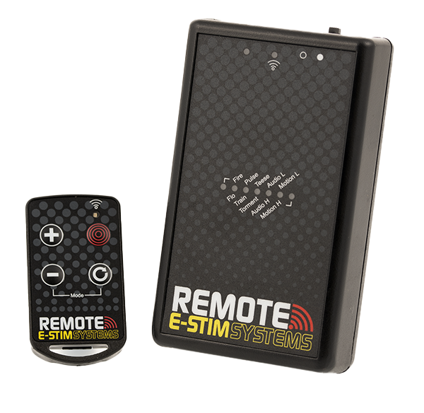 The new E-Stim Systems Remote system consists of two units, a small hand held 'key fob' style transmitter and the Power Unit radio receiver. The Power Unit is connected to an electrode that is attached or inserted into your subject, whilst the Keyfob transmitter provides the control from a distance of up to 50M (~150ft). The Pack also consists of a set of sticky pads, a 2mm/TENS connection cable, and a battery for the Power Unit (the battery for the Keyfob (CR2032) is already fitted). A quick guide is now also provided to give you a quick insight into the controls useful for when you don't have access to this online manual.
The distance over which the Power Unit will respond to the Keyfob transmitter is highly dependent on the environment, battery levels, and a number of other factors.
The remote allows 27 levels of output in 10 different modes. All controls including level and mode selection are via a simple up/down/select system on the Keyfob.
The system also allows the use of multiple Keyfobs and receivers. As each Keyfob generates a unique code, it is possible to 'teach' a Power Unit to respond to a number of Keyfobs, and conversely, it is also possible to have a number of receivers responding to a single Keyfob .
Before Use
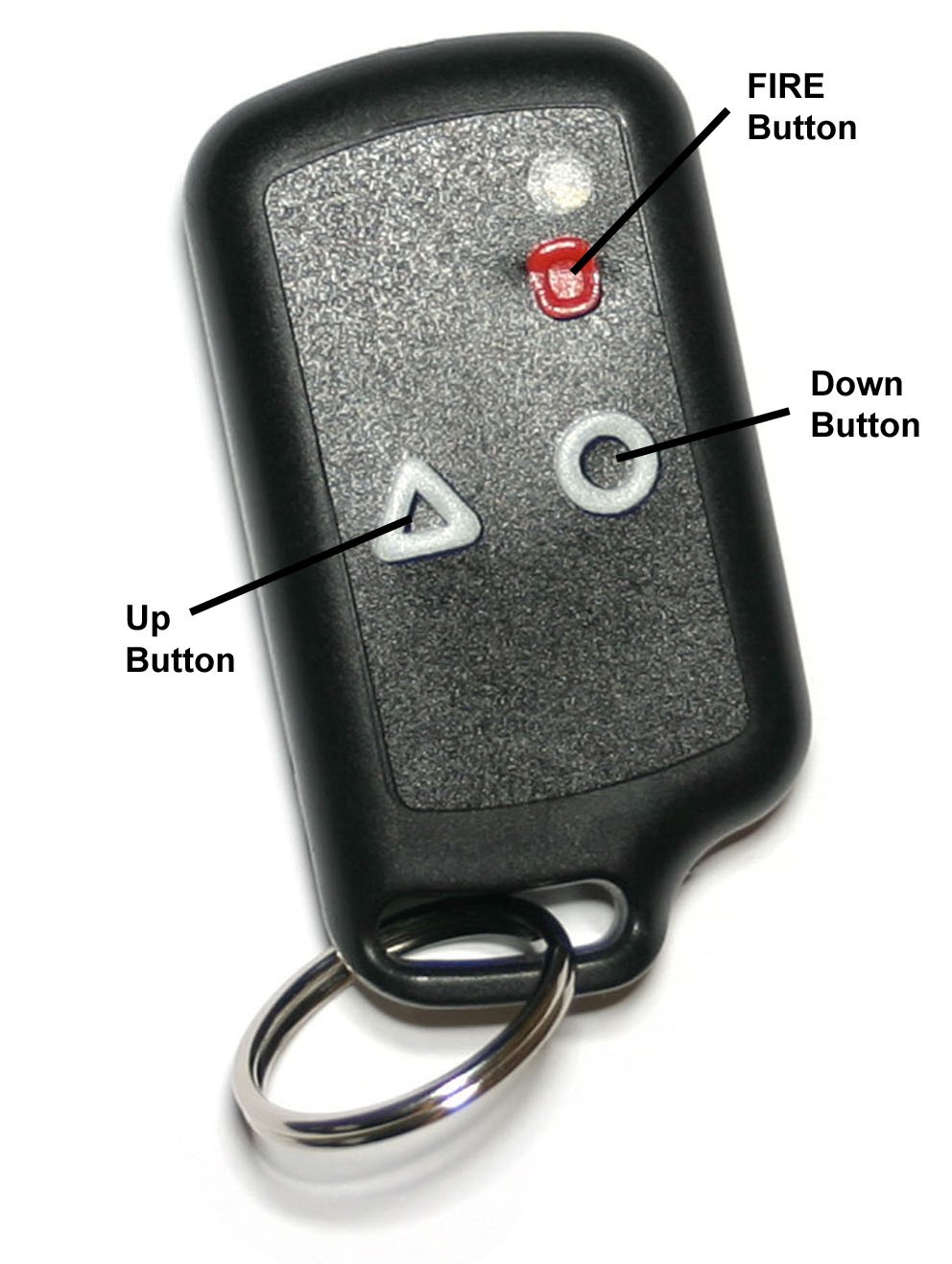
Before you can use your E-Stim Systems Power Unit you need to ensure that the Power Unit has recognised and is responding to the Keyfob . If you insert a battery into the receiver, switch the unit on with no electrodes connected and press the red button on the Keyfob , two LED's should light on the receiver. The RX LED should flicker and the output LED should illuminate for the period of time the red button on the Keyfob is depressed.
If the activity LED flickers but the output LED does not illuminate, this indicates that the Power Unit has not recognised the Keyfob . In this case you need to follow the LEARN procedure.
Startup
On startup the Power Unit will perform a self test and display the battery level before selecting the last mode used. The remote system now remembers the previous mode the unit was in last time it was switched off, as well as the adjustment level. To reset the unit to Factory setting, follow the Factory reset procedure. The output level will always be set to zero when the Power Unit is switched on.
Using the Remote System
 Step 1 Fit the batteries The Keyfob is supplied with the battery fitted.
Step 2 Ensure the Keyfob is linked to the Power Unit (Learn Mode)
Familiarise yourself with the controls on the Keyfob.
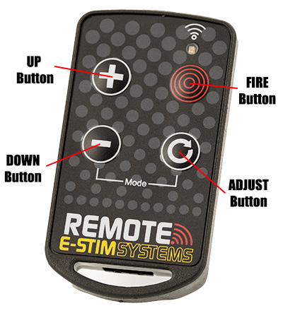
Depending on the mode generally the UP button increases the output level, the DOWN button decreases the output level, and the FIRE button activates or overrides the output, depending on the current mode selected. The ADJUST Button provides adjustment in each mode. In Training Mode, the Down button gives 25% output, the Adjust button gives 50% output, the UP Button gives 75% out and and the Fire button gives 100% output.
Pressing both the DOWN and ADJUST buttons together will switch the unit into mode select. See Mode Control.
Holding a level button will increase or decrease the output in larger steps. If you hold a button down for more than around 30 seconds the Keyfob will automatically shut down to save batteries (This is designed to stop inadvertent activation of the Keyfob in a pocket). If this occurs, simply release the button and press again.
If the LED on the Keyfob appears dim, and range is reduced then the Keyfob battery may need to be replaced.
Connecting an electrode
Ensure the Power Unit is turned off, and connect a suitable electrode via the output socket. Connect an electrode to a suitable section of the body. (DO NOT CONNECT THE Power Unit UNIT OR ANY ELECTRICAL DEVICE TO ANY LOCATION ABOVE THE WAIST (ACROSS THE ARMS COUNTS AS ABOVE THE WAIST!), BUT ESPECIALLY DO NOT CONNECT ACROSS THE HEART, CHEST, NECK OR HEAD. DO NOT USE IF FITTED WITH A PACEMAKER OR ARE PREGNANT. REMEMBER YOU USE THIS DEVICE AT YOUR OWN RISK.
Turn the Power Unit on, the output LED should flash 4 times and automatically select the previous mode 1 and then press the red button. Your subject may feel a slight tingling sensation from the electrode site. If not increase the level and try again. Adjust the output level as required.
If you or your subject experiences any pain or discomfort then stop using immediately. If we recommend the use of conductive lubrication as any E-Stim device is potentially capable of causing burning when used on sensitive and or small contact areas at high output levels.
Always ensure all connections are secure and free from corrosion.
DO NOT SHORT CIRCUIT the output. DO NOT attempt to open the Power Unit unit. High voltages are present even when the unit is switched off and there are no user serviceable parts inside. Opening the Power Unit will invalidate your guarantee.
Fitting Batteries
Both the Keyfob and the Power Unit require batteries to operate. The Keyfob is supplied fitted with a battery, whilst the Power Unit unit needs to have a battery fitted (not supplied).
Fitting a battery (Power Unit)

Ensure the unit is switched off, and any electrodes connection cables are disconnected.
Turning the unit over press gently down on the center of the battery cover and slide the cover downwards.
Remove the old battery (if fitted) and replace with a fresh alkaline PP3. The battery connector is polarized so it should not be possible to connect the battery incorrectly, but ensure the polarity is correct before attempting connection.
Place the battery into the unit and replace the battery compartment cover. The cover will slide and then should then click into position.
Turn the unit over. The unit is now ready for operation.
Please note we do NOT recommend the use of Zinc Carbon or standard re-chargeable batteries in the E-Stim Systems Remote Power Unit. NiMh re-chargeable batteries, with a terminal voltage of 8.4V or above may be used with a possible reduction in output power.
In the event the Power Unit is not being used for a period of time, remove the battery to avoid any possible damage due to batter leakage.
Fitting a battery (Keyfob)
Before changing the battery ensure that the Power Unit unit is turned off and disconnected from any electrodes. The Keyfob is supplied with a battery (CR2032) installed.
In order to replace the battery, use a small 'Phillips' or cross head type screwdriver to unscrew the two screws on the back of the Keyfob , being careful not to loose them.
Open the case and gently remove the battery. Insert the new battery, noting the polarity marked by a '+' on the board and the battery and close the case.
Replace the screws and screw the Keyfob back together.
Check that the battery has been correctly inserted by pressing a button on the Keyfob (ensuring that any Power Unit in range is turned off). The yellow LED on the Keyfob should flash for the duration of the press. In the event that it does not, check you have replaced the battery correctly.
<changing battery keyfob pictures coming soon>
Level Control
in general most modes use the up and down buttons to control the level. When the level is selected the level is displayed on the status bar, unless you are in Discreet Mode. As we need to display 28 levels (we don't count zero as an actual level but it is), and need to show 4 different levels between each led. As the level increases the status display will show a growing bar graph with each successive LED flashing slowly, flashing faster, flashing even faster then switching to a solid glow. Then the next LED in the display will continue the cycle. As an example
| Slow Flash | 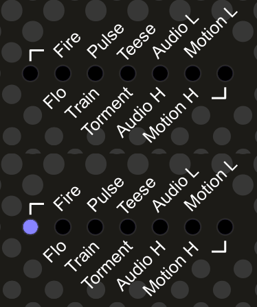 |
Level 1 |
| Medium Flash | 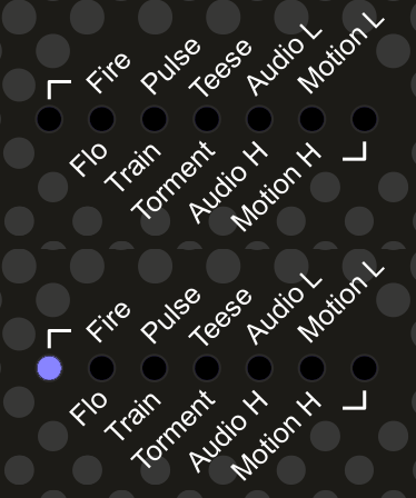 |
Level 2 |
| Fast Flash | 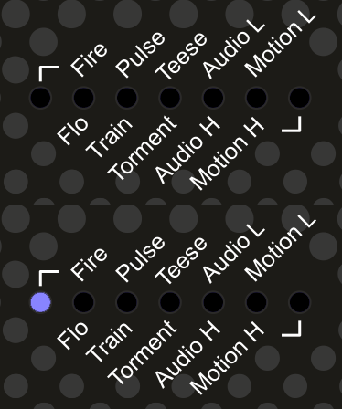 |
Level 3 |
| Solid | 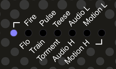 |
Level 4 |
Pressing and holding the UP or DOWN button will result in the level jumping to the next 4th step i.e. 4 8 12 16 20 etc etc. Pressing and holding the DOWN button continuously will eventually result in the zero level being reached, when a quick LED wipe will display.
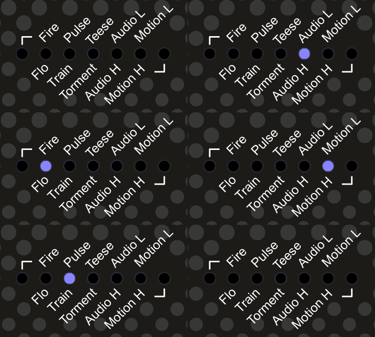
In Discreet mode the level display is not shown.
Adjustment Control
Most modes have some form of adjustment. Repeatedly pressing and releasing the ADJUST button will cycle through the individual adjustment for the current mode.The effect of the actual adjustment will depend on the mode. The adjust dot display will show for a couple of seconds after the adjust button has been released.
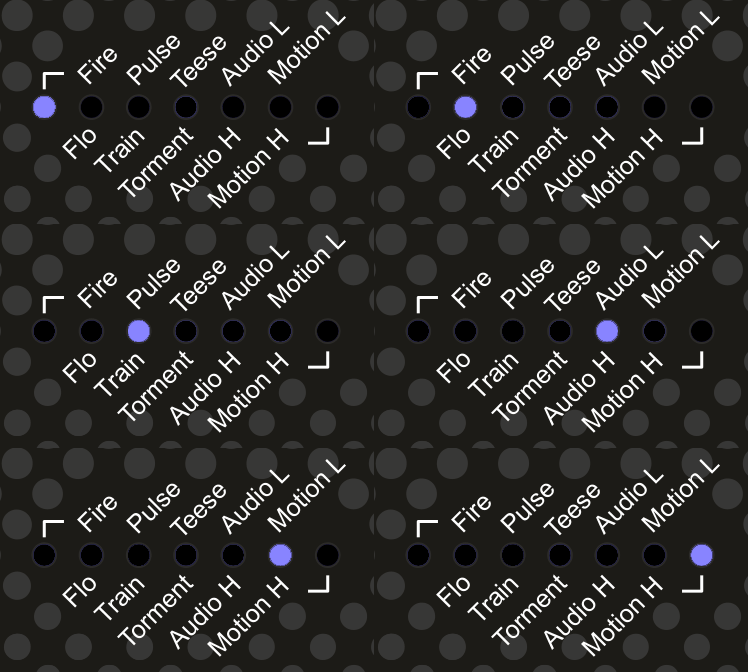
If Discreet mode has been selected, the adjust dot display will not show.
Mode Control
Mode Selection
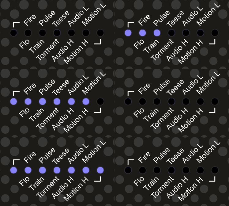
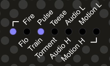
Pressing both DOWN and ADJUST buttons on the keyfob together AT THE SAME TIME will switch the Power Unit into mode selection mode, indicated by a two solid LEDs showing on the status bar on the receiver. The position of the LEDs will indicate the current mode, the left on the far left indicates modes on the top row can be selected, the LED on the far right indicates modes on the bottom row can be selected. A mode is not selected until the ADJUST button has been pressed.
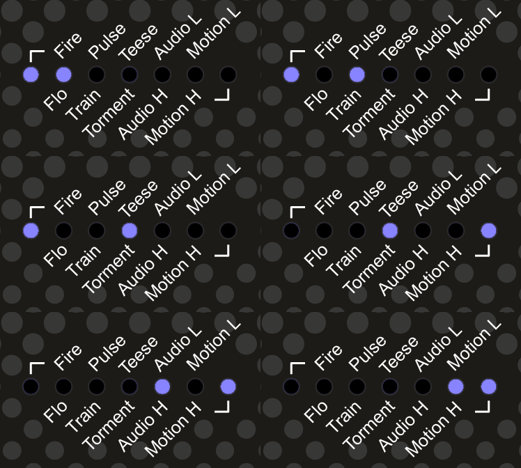
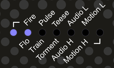
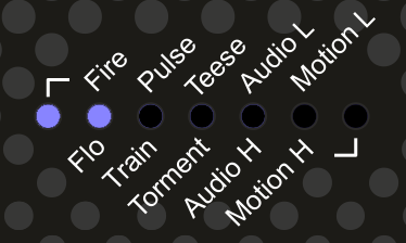
Pressing either the UP button or DOWN buttons will cycle up and down through the modes. Pressing the ADJUST button will activate the currently selected mode. The mode is not active until it has been selected. The mode is indicated by the left or right LED showing if you are on the top or bottom of the list of modes, and then a second LED showing the mode. As an example this is FIRE mode.
And this is Flo Mode
When the mode has been selected the status display will flash 3 times and then the output level is automatically set to zero. and the Adjust value set to 1. The current mode is remembered when the Power Unit is switched off.
The modes are as follows.

Fire Mode
The classic remote control mode. The UP and DOWN buttons control the output level (Zero to 27), whilst pressing the FIRE button will activate the output at the selected level as well as showing the output level on the Status display (unless you are in Discreet mode). The output will be active for the time the fire button is pressed, however the Keyfob will timeout after around 25 - 30 seconds cutting the output. The output LED will only be illuminated when the output is active. The Adjust button changes the feel of the output over 7 different values.

Flo Mode
A continuous output mode. The UP and DOWN buttons control the output level (Zero to 27), whilst pressing the FIRE button will give a boosted output 4 levels higher than the current setting (assuming there are any levels left and assuming your level is not set to zero. If the Power Unit is set to Level Zero then the output will not operate in boost mode when the fire button is pressed. ) Adjust cycles through several different ‘feelings’. Helix. In operation the Output LED will be on continuously. The Level output is not shown in Discreet Mode.
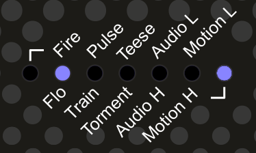
Pulse Mode
A pulsed output mode. The UP and DOWN buttons control the output level (Zero to 27), whist pressing the ADJUST button will cycle through 7 different pulse speeds from slow to fast. The FIRE button will override the output to give a continuous output. Level output is not shown in Discreet Mode.
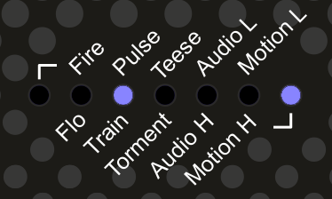
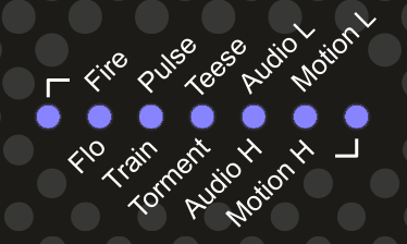
Training Mode
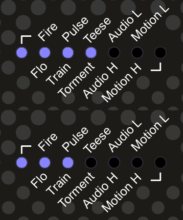
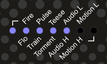
The Classic 'Training Mode' No need to worry about what level the output is when you press the first button, as the outputs are preselected. DOWN Button gives 25% output, ADJUST 50% UP 75% and FIRE 100%. Assuming you are not using discreet mode the status display bar will indicate the output level.
 |
 |
 |
 |
| 25% | 50% | 75% | 100% |
Teese
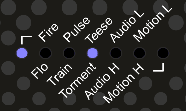 A continuous output mode with a rising feel, indicated by a moving LED on the status bar. Once a cycle is complete it starts from zero. UP and DOWN buttons control the level, and the FIRE button boosts the output 4 steps above the current output. The boost does not work if the output level is set to zero. The ADJUST button control the speed of the cycle with 7 different speeds available.
Torment
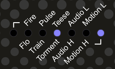 A continuous output mode with a rising and dropping feel, indicated by a moving LED on the status bar. Once a cycle is complete the cycle reverses. UP and DOWN buttons control the level, and the FIRE button boosts the output 4 steps above the current output. The boost does not work if the output level is set to zero. The ADJUST button control the speed of the cycle with 7 different speeds available.
Audio Modes
Audio modes use sound to activate the output. The nature of the sound, the distance the sound source is from the Power unit , the level and the settings of the power unit in temrs of mode and adjustment selected all will effect how the sound is felt as an E-Stim sensation.
Audio Low Mode
Uses the inbuilt microphone to trigger the output. The ADJUST button controls the response, from highly sensitive to less sensitive. The Level controls UP and DOWN provide a multiple of the input so a maximum input with the level set to 27 (Full) will give the maximum output, where the same input with the level set to 14 will give half that output. The FIRE button artificially overrides the input giving the equivalent of a 100% input. Audio Low mode is not as sensitive as the Audio High Mode and is better used in more noisy environments.
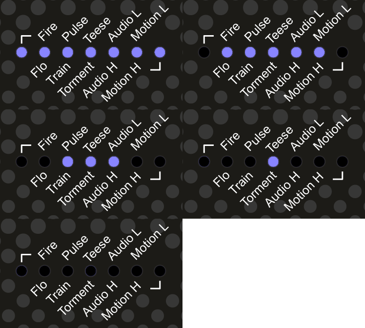
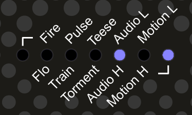 Audio High Mode
Uses the inbuilt microphone to trigger the output with a higher sensitivity than the Audio Input Low mode. UP and DOWN button control the level out the output, ADJUST controls the sensitivity and FIRE overrides the output.There are 7 levels of adjustment via the ADJUST control. The display is different to the Audio Low mode as it is a bargraph increasing from the left side giving a more sensitive display. The FIRE button artificially overrides the input giving the equivalent of a 100% input.
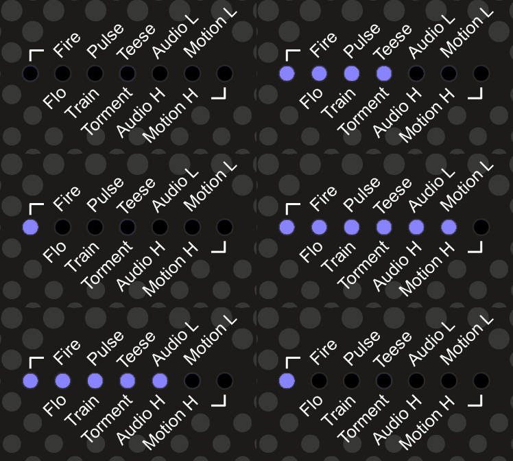
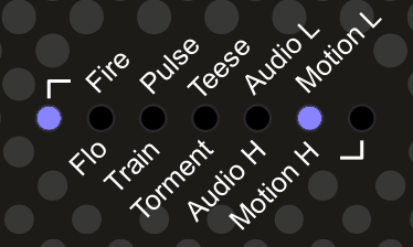
Motion Low Mode
Motion Sensitive mode. The UP and DOWN buttons control the output level (1-27), whilst pressing the FIRE button will override the motion trigger and activate the output. If the Power Unit is moved excessively then the output will trigger. WARNING it is very sensitive!!. In operation the output LED will flicker when the output is active.
The motion sensor is very sensitive. In use the internal microprocessor counts the number of times the sensor is triggered and when this reaches a set level the output will fire. As the level builds up the bargraph will increase. Once all 7 bars are illuminated the Output will trigger. The trigger point is adjustable depending on the adjust setting. should no movement occur then the bargraph display will gradually decay over time. Pressing the FIRE button will override the output and ‘zap’ the subject, possibly causing even more movement!!
The motion sensor is active in any orientation.

Receiver
The Power Unit has two simple controls and 3 Displays.
Power Unit Displays
|
LED |
Use |
|
Output |
Indicates output activity and mode. In mode select mode, the number of flashes indicates the mode. On startup the Output LED will flash 3 times in quick succession. |
| Status Bar | Used to indicate the battery level, current output level, mode and adjustment |
|
RX |
Indicates Radio activity. Will also indicate when the Power Unit is in LEARN mode. Note that the RX LED will indicate activity when any compatible Keyfob is used within range, even if that Keyfob has not been learnt by the receiver. |
Power Unit Controls
|
Control Button |
Use |
|
Top Slide Switch |
Powers the unit on and off. |
|
Learn button (inside the battery compartment.) |
Used during the LEARN procedure. |
Power Unit Outputs
|
Output |
Use |
|
3.5mm mono socket |
Voltage output to electrode. |
LEARN Mode
What is it?
Learn mode allows the user to select which Keyfobs the Power Unit will respond to. It is possible to 'teach' a Power Unit to respond to up to 50 separate Keyfobs, and it is also possible to teach more than one Power Unit to respond to the same Keyfob .
The Power Unit is initially supplied with one Keyfob that is linked with the Power Unit during testing, and should operate 'out of the box'. Learn mode is generally only needed if you have purchased replacement or additional Keyfobs or receivers
The learn button is inside the battery compartment. Open the Battery Compartment, remove the battery, but do not disconnect it, and you should find the learn button inside. The learn button will only operate when the Power Unit has a battery connected and is powered on, so DO NOT DISCONNECT THE BATTERY.
Clearing the Power Unit memory
Clearing all Keyfobs. This will remove all Keyfob s from the Power Unit memory.
Remove the battery from the battery compartment but ensure that it is still connected. Turn the power unit on. Hold down the learn button for at least 10 seconds. The RX LED will illuminate. Release the learn button. The RX LED should now blink around 10 times and then stop. The memory has now been cleared.
Teaching the Power Unit to recognise a remote.
Remove the battery from the battery compartment but ensure that it is still connected. Turn the power unit on.
Press the learn button once. The RX LED should illuminate. Press a button on the Keyfob you wish to use with the receiver. The RX LED should now go out. press the button again. The RX LED should now blink several times. The Power Unit has now 'learnt' the Keyfob and will now respond to the Keyfob. Additional Keyfobs can also be added so one Power Unit will respond to more than one Keyfob. It is also possible to add a single Keyfob to more than one Power Unit giving even more possibilities.
Outputs
Connection to electrodes is via a single 3.5mm mono jack socket on the top of the receiver. Ensure the unit is switched off before inserting or removing the connection jacks to eliminate the possibility of either inadvertent electric shocks or short circuits occurring. We recommend the use of E-Stim Systems 3.5mm Right Angled connectors as this will reduce the possibility of damage occuring to the output socket.
Adapters are available for 2mm and 4mm connectors.
Extra Controls
Factory Reset
Both the current mode and the adjustment setting for that mode are remembered when the receiver is switched off. To reset the Power Unit back to a factory default of FIRE mode and adjustment setting of 1, Press and hold the DOWN button when switching the unit on. The unit will then show three fast dot 'zips' from right to left and then reset the mode to FIRE and the adjustment to 1. Output levels are always set to zero when the Power Unit is first switched on.\
Discreet Mode
Discreet mode switches the status bar off for discreet play. Simply press and hold the ADJUST button on the keyfob when switching the Power Unit on. The Status display will then show two fast dot 'zips' from low to high' and then the battery status before switching the status display off. From then on the status display will only illuminate for mode changes. To switch discreet mode off simply switch the Power Unit off and then on again. Discreet mode is not remembered when the unit is switched off.
<<discreet mode active>>
Accessories
The E-Stim Systems Remote System Pack is supplied in a custom fitted carry case with:-
- The Power unit (Receiver).
- A Keyfob (Fitted with a CR2032 Battery)
- A 1.5M connection cable fitted with a 3.5mm right angled jack plug on one end (for connection to the Power Unit unit) and two colour coded 2mm plugs on the other, to connect to E-Stim Electrodes fitted with 2mm or TENS style sockets.
- A Quick Guide Card.
- A pack of re-usable self adhesive 'Sticky Pads'.
- 1 PP3 Battery for the Power Unit.
A wide range of electrodes and other accessories are available. For more information visit our website and online stores at
For customers in the UK & EU https://www.e-stim.co.uk
For customers in the USA, Canada, Australia and the rest of the world https://www.e-stimsystems.com
Additional Notes
Storage
In the event that the E-Stim Systems Remote System is not going to be used for a period of time always remove the battery to avoid any possibility of damage being caused by battery leakage. The Keyfob is supplied with a high quality battery, that should not leak, but it is still recommended that they are removed if the units are not being used for a long period. Keep the batteries away from Children and do not swallow them!!
Cleaning
DO NOT use solvents to clean either the Keyfob or the Power Unit. A gentle wipe with a soft cloth should be sufficient. It is not possible to sterilise either unit.
Belt Clip
The E-Stim Systems Remote Power Unit is fitted with a belt clip. This clip is designed to clip on a belt or harness and should not be over extended.
Specifications
Receiver
|
Channels/ Outputs |
Dynamic Drive, Single Channel, via an industry standard mono 3.5mm socket. |
|
Display
|
9 High Brightness Light Emitting Diodes indicating Transmitter Activity, Output Activity and Status. |
|
Operating Modes |
27 Levels in 10 modes, including 2 Audio Modes and 2 Motion Sensitive modes |
|
Controls
|
Slide switch for Power On/Off. Push button for LEARN mode (insider battery compartment) Non Mercury Vibration Sensor (Internal) |
|
Output Waveform |
High Voltage current limited, pulsed AC with Dynamic width output waveforms. |
|
Power Supply |
Standard 9 Volt Alkaline (PP3) |
|
Battery Life |
Variable dependent on load and input, but estimated at around 8 hours with continuous use. |
|
Dimensions (approx.) |
112mm x 65mm x 41mm |
|
Weight (with battery) |
146g |
Keyfob Transmitter
|
Type |
4 Button custom Keyfob transmitter with Auto Power Off |
|
Frequency |
KEELOQ Encoded AM 433.92Mhz |
|
Range |
Up to 100M under optimum conditions |
|
Dimensions |
32.7mmm x 59mm x8mm |
|
Weight (with Battery) |
17g |
|
Power Supply |
3V (CR2032) |
| Protection | IP68 |
Problems?
In the unlikely event you have problems with the operation of your E-Stim Systems Remote System, or any of the supplied accessories, then contact your original supplier or email This email address is being protected from spambots. You need JavaScript enabled to view it. quoting the serial number and the problem you have encountered. There are no user serviceable parts inside and the breaking of any seals with invalidate your guarantee.
Lifetime Guarantee
All units are covered by our Lifetime Guarantee, against failure due to manufacturing defects for the lifetime of the unit subject to normal use.
The Guarantee includes the cost of parts and labour, does not include shipping and only applies to the original purchaser. Proof of purchase may be required.
|
SAFETY WARNING DO NOT CONNECT THE E-STIM SYSTEMS REMOTE Power Unit OR ANY ELECTRICAL DEVICE TO ANY LOCATION ABOVE THE WAIST (ACROSS THE ARMS COUNTS AS ABOVE THE WAIST!), BUT ESPECIALLY DO NOT CONNECT ACROSS THE HEART, CHEST, NECK OR HEAD. DO NOT USE IF FITTED WITH A PACEMAKER OR ARE PREGNANT. REMEMBER YOU USE THIS DEVICE AT YOUR OWN RISK. YOU MUST READ AND UNDERSTAND THE USER MANUAL AND ALL OTHER INSTRUCTIONS BEFORE ATTEMPTING OPERATION. |
Certificate of Conformity
US Regulatory Wireless Notice
This device compiles with Part 15 of the FCC Rules. Operation is subject to the following two conditions: (1) this device may not cause harmful interference, and (2) this device must accept any interference received, including interference that may cause undesired operation.
The FCC requires the user to be notified that any changes or modifications made to the device that are not expressly approved by E-Stim Systems Ltd may void the users authority to operate the equipment.
European Union Notice
Products bearing the CE marking comply with the R&TTE Directive (2014/53/EU), EMC Directive (2014/30/EU), and the Low voltage Directive (2014/35/EU) issued by the Commission of the European Community.
Compliance with these directives implies conformity to the following European norms (in parentheses are the equivalent international standards and regulations.)
EN 55022 (CISPR 22) – Electromagnetic Interference,
EN 55024 (IEC61000-4-2,3,4,5,6,8,11) – Electromagnetic Immunity, and,
EN 60950 (IEC 60950) – Product Safety.
Europe: The transmitters use ECM compliant radio transmitter modules and comply with ETSI330-220 and ETSI300-683.
This device may be used in all European Union Countries.
All images and text within this manual are ©E-Stim Systems Ltd 2020
All rights reserved.
E & OE.
Classic Remote User Manual
Welcome
Congratulations on purchasing an E-Stim Systems Series 1 Remote System. Given sufficient care your Remote Kit should give you many years of erotic electro stimulated pleasure. Before starting always read the instructions and ensure you are completely familiar with all of the controls and the safety warnings prior to use.
Quick Links
Key Features
- 5 adjustable control modes, with 21 output levels, all controlled from a simple and discrete keyfob style transmitter.
- Unique Motion Sensor
- Uniquely digitally encoded transmitters. Receivers will not respond to other radio sources.
- Up to 50M (~150ft) range
- Learn mode allows multiple transmitters to be used in combination as well as multiple receivers.
- Single channel output allows the use of unipolar and bipolar electrodes.
- Current limited AC output to ensure safety and avoid the possibility of electrode polarisation.
|
SAFETY WARNING DO NOT CONNECT THE E-Stim Systems Series 1 Remote Receiver OR ANY ELECTRICAL DEVICE TO ANY LOCATION ABOVE THE WAIST (ACROSS THE ARMS COUNTS AS ABOVE THE WAIST!), BUT ESPECIALLY DO NOT CONNECT ACROSS THE HEART, CHEST, NECK OR HEAD. DO NOT USE IF FITTED WITH A PACEMAKER OR ARE PREGNANT. REMEMBER YOU USE THIS DEVICE AT YOUR OWN RISK. YOU MUST READ AND UNDERSTAND THE USER MANUAL AND ALL OTHER INSTRUCTIONS BEFORE ATTEMPTING OPERATION. |
What's in the kit?
Contents
 The E-Stim Systems Series 1 Remote system consists of two units, a small hand held 'key fob' style transmitter and a receiver. The receiver is connected to an electrode that is attached or inserted into your subject, whilst the transmitter provides the control from a distance of up to 50M (~150ft).
The distance over which the receiver will respond to the transmitter is highly dependent on the environment, battery levels, the position of the aerial and a number of other factors.
Quick Guide
The remote allows 21 levels of output in 5 different modes. All controls including level and mode selection are via a simple up/down/select system on the transmitter..
The system also allows the use of multiple transmitters and receivers. As each transmitter generates a unique code, it is possible to 'teach' a receiver to respond to a number of transmitters, and conversely, it is also possible to have a number of receivers responding to a single transmitter.
Before Use
Before you can use your E-Stim Systems receiver kit you need to ensure that the receiver has recognised and is responding to the transmitter. If you insert a battery into the receiver, switch the unit on with no electrodes connected and press the red button on the transmitter, two LED's should light on the receiver. The activity LED should flicker and the output LED should illuminate for the period of time the red button on the transmitter is depressed.
If the activity LED flickers but the output LED does not illuminate, this indicates that the receiver has not recognised the transmitter. In this case you need to follow the LEARN procedure.
Using the Remote Kit
Ensure transmitter is linked to the receiver (Learn Mode)
Familiarise yourself with the controls on the transmitter. In Modes 1 to 4, The left button increases the output level, or increases the mode, the right button decreases the output level or decreases the mode, and the red button either activates or adjusts the output, depending on the current mode selected. In Mode 5 (Training Mode), the Up button give 33% output, the Down button gives 66% output, and the Fire button gives 100% output.
Pressing both the left and right buttons together will switch the unit into mode select.
Do not hold down any button for any length of time. This will only drain the battery in the transmitter. If you hold a button down for more than around 30 seconds the transmitter will automatically shut down to save batteries (This is designed to stop inadvertent activation of the transmitter in a pocket). If this occurs, simply release the button and press again.
If the red LED on the transmitter appears dim, and range is reduced then the transmitter battery may need to be replaced.
Connecting an electrode
Ensure the receiver is turned off, and connect a suitable electrode via the output jacks. Connect an electrode to a suitable section of the body. (DO NOT CONNECT THE RECEIVER UNIT OR ANY ELECTRICAL DEVICE TO ANY LOCATION ABOVE THE WAIST (ACROSS THE ARMS COUNTS AS ABOVE THE WAIST!), BUT ESPECIALLY DO NOT CONNECT ACROSS THE HEART, CHEST, NECK OR HEAD. DO NOT USE IF FITTED WITH A PACEMAKER OR ARE PREGNANT. REMEMBER YOU USE THIS DEVICE AT YOUR OWN RISK.
Turn the receiver on, the output LED should flash 4 times and automatically select mode 1 and then press the red button. Your subject may feel a slight tingling sensation from the electrode site. If not increase the level and try again. Adjust the output level as required.
If you or your subject experiences any pain or discomfort then stop using immediately. If we recommend the use of conductive lubrication as any E-Stim device is potentially capable of causing burning when used on sensitive and or small contact areas at high output levels.
Always ensure all connections are secure and free from corrosion.
DO NOT SHORT CIRCUIT the output. DO NOT attempt to open the receiver unit. High voltages are present even when the unit is switched off and there are no user serviceable parts inside. Opening the receiver will invalidate your guarantee.
Fitting Batteries
Both the transmitter and the receiver require batteries to operate. The transmitter is supplied fitted with a battery, whilst the receiver unit needs to have a battery fitted (not supplied).
Fitting a battery (Receiver)
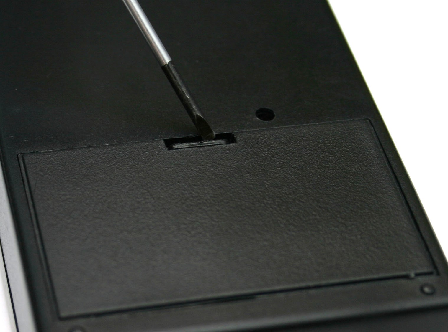 Ensure the unit is switched off, and any electrodes connection cables are disconnected.
Turning the unit over and using a small screwdriver or a fingernail inserted into the battery compartment slot, gently prise the battery compartment cover out.
Remove the old battery (if fitted) and replace with a fresh alkaline PP3. The battery connector is polarized so it should not be possible to connect the battery incorrectly, but ensure the polarity is correct before attempting connection.
Place the battery into the unit and replace the battery compartment cover. The cover is fitted with two tabs which insert into the lower half of the case first, then the top half of the cover will then clip into position.
Turn the unit over. The unit is now ready for operation.
Please note we do NOT recommend the use of Zinc Carbon or standard re-chargeable batteries in the E-Stim Systems Series 1 Remote Receiver. NiMh re-chargeable batteries, with a terminal voltage of 8.4V or above may be used with a possible reduction in output power.
In the event the receiver is not being used for a period of time, remove the battery to avoid any possible damage due to batter leakage.
Fitting a battery (Transmitter)
Before changing the battery ensure that the receiver unit is turned off and disconnected from any electrodes. The transmitter is supplied with a battery installed.
In order to replace the battery, use a small 'Phillips' or cross head type screwdriver to unscrew the two screws on the back of the transmitter, being careful not to loose them.
Open the case and gently remove the battery from the two clips. Insert the new battery, noting the polarity marked by a '+' on the board and the battery and close the case.
Replace the screws and screw the unit together.
Check that the battery has been correctly inserted by pressing a button on the transmitter (ensuring that any receiver in range is turned off). The red LED on the transmitter should flash for the duration of the press. In the event that it does not, check you have replaced the battery correctly.
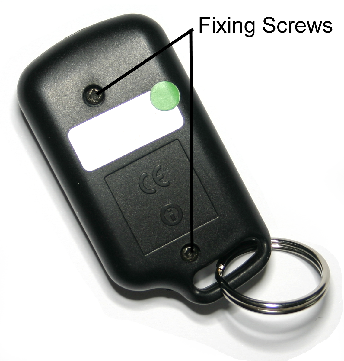
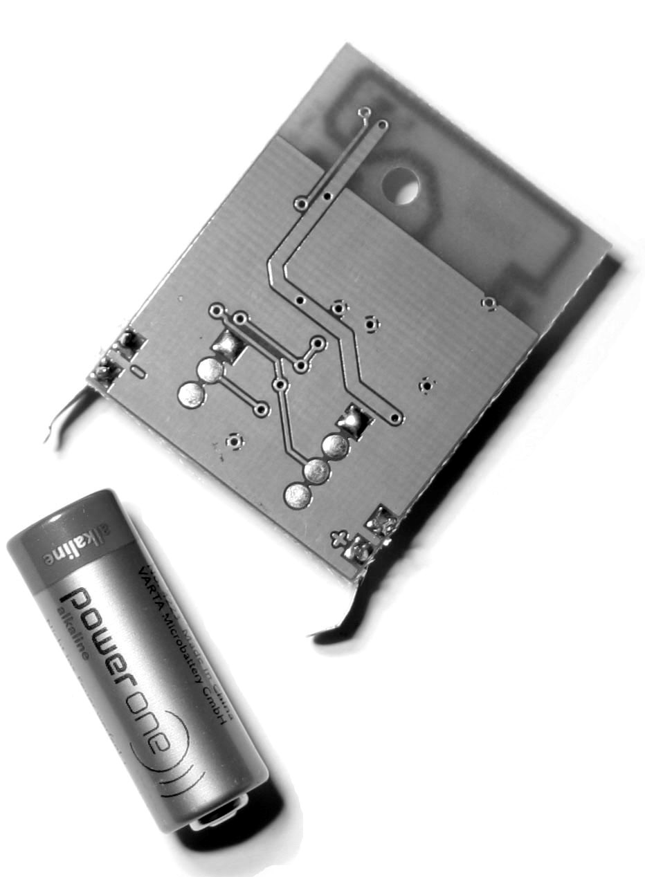
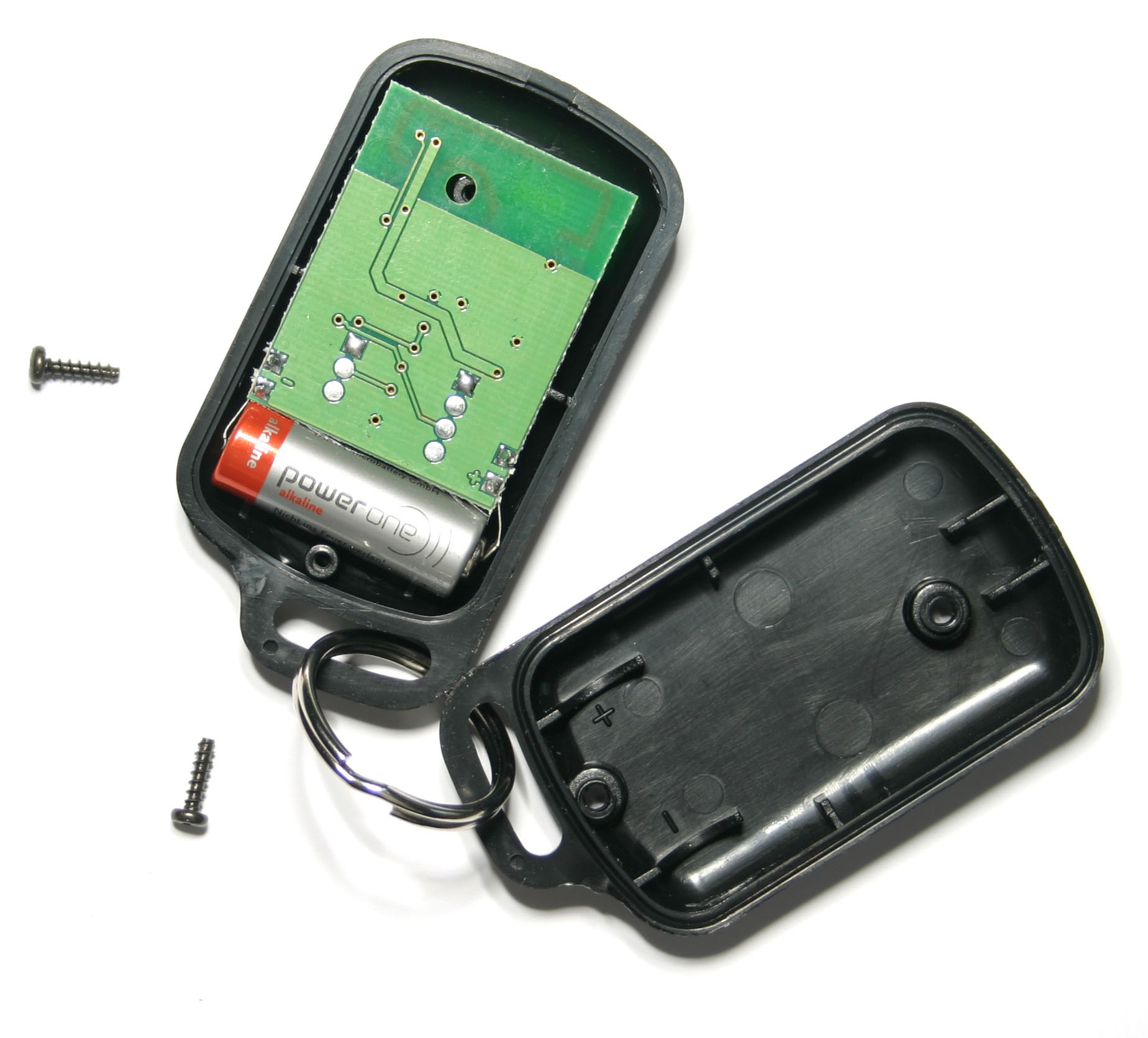
Mode Control
Selection
Pressing both left and right buttons together at any time will switch the receiver into mode selection mode, indicated by a flashing output LED on the receiver. The number of flashes indicates the currently selected mode. During mode selection the output is automatically turned off.
|
Number of |
Mode |
|
1 |
Fire mode. |
|
2 |
Continuous |
|
3 |
Pulse mode |
|
4 |
Motion Mode |
|
5 |
Training Mode |
The remote system allows the user to switch the output between 21 different levels in 5 different modes.
Pressing either the left button or right buttons will cycle up and down through the modes. Pressing the red fire button will activate the currently selected mode.
When the mode has been selected the output level is automatically set to the lowest level (1).
Mode 1 – Fire
The classic remote control mode. The left and right buttons control the output level (1-21), whist pressing the fire button will activate the output at the selected level. The output will be active for the time the fire button is pressed, however the transmitter will timeout after around 23 seconds. The output LED will only be illuminated when the output is active. When the unit is first turned on it will be in mode 1.
Mode 2 – Continuous
Continuous output mode. The left and right buttons control the output level (1-21), whist pressing the fire button will cycle through several different ‘feelings’. This is roughly equivalent to the pulse period control on an ElectroHelix. In operation the Output LED will be on continuously.
Mode 3 – Pulse
Pulse output mode. The left and right buttons control the output level (1-21), whist pressing the fire button will cycle through several different pulse speeds. In operation the output LED will display the pulse rate.
Mode 4 – Motion Sensor
Motion Sensitive mode. The left and right buttons control the output level (1-21), whilst pressing the fire button will override the motion trigger and activate the output. If the receiver is moved excessively then the output will trigger. WARNING it is very sensitive!!. In operation the output LED will flicker when the output is active.
The motion sensor is very sensitive. In use the internal microprocessor counts the number of times the sensor is triggered and when this reaches a set level the output will fire. Thus slow cumulative movement over time will trigger the unit as will sharp shocks. Pressing the fire button will override the output and ‘zap’ the subject, possibly causing even more movement!!
The motion sensor is active in any orientation.
Mode 5 – Training Mode
Training Mode. The left button on the transmitter is set to 33% (Level 7), the right button is set to 66% (Level 14) and the red fire button will give 100% (Level 21). The output will be on for as long as the button is pressed down (for upto around 30 seconds). In operation the output LED will light when the output is active.
Use with Care!!!!
Receiver
The receiver has two simple controls and 3 LED's.
Receiver Displays
|
LED |
Use |
|
Power |
When on the receiver is powered up. |
|
Output |
Indicates output activity and mode. In mode select mode, the number of flashes indicates the mode. On startup the Output LED will flash 3 times in quick succession. |
|
RX |
Indicates transmitter activity. Will also indicate when the receiver is in LEARN mode. Note that the RX LED will indicate activity when any compatible transmitter is used within range, even if that transmitter has not been learnt by the receiver. |
Receiver Controls
|
Control Button |
Use |
|
Top Slide Switch |
Powers the unit on and off. |
|
Learn button on reverse of receiver. |
Used during the LEARN procedure. (See Page 14) |
Receiver Outputs
|
Output |
Use |
|
3.5mm mono socket |
Voltage output to electrode. |
LEARN Mode
What is it?
Learn mode allows the user to select which transmitters the receiver will respond to. It is possible to 'teach' a receiver to respond to up to 50 separate transmitters, and it is also possible to teach more than one receiver to respond to the same transmitter.
The receiver is initially supplied with one transmitter that is linked with the receiver during testing, and should operate 'out of the box'. Learn mode is generally only needed if you have purchased replacement or additional transmitters or receivers
The learn button is in a small hole on the back of the receiver, just above the battery compartment.
Clearing the receiver memory
Clearing all transmitters. This will remove all transmitters from the receivers memory.
Hold down the learn button for at least 10 seconds. The RX LED will illuminate. Release the learn button. The RX LED should now blink around 10 times and then stop. The memory has now been cleared.
Teaching the receiver to recognise a remote.
Press the learn button once. The RX LED should illuminate. Press the red button on the transmitter you wish to use with the receiver. The RX LED should now go out. press the button again. The RX LED should now blink several times. The receiver has now 'learnt' the transmitter and will now respond to it.
Outputs
Connection to electrodes is via a single 3.5mm mono jack socket on the top of the receiver. Ensure the unit is switched off before inserting or removing the connection jacks to eliminate the possibility of either inadvertent electric shocks or short circuits occurring. Adapters are available for 2mm and 4mm connectors.
The connection cable will be come detached from the receiver if pulled. This is a safety feature as disconnection will result in the voltage being removed from the electrodes. If you find this to be a problem during play, then we suggest you use slightly longer cables.
Accessories
The E-Stim Systems Series 1 Remote Kit is supplied in a custom fitted carry case with:-
- A Remote Receiver.
- A Key fob Transmitter (Fitted with a Battery)
- A 1.5M connection cable fitted with a 3.5mm jack on one end (for connection to the receiver unit) and two colour coded 2mm plugs on the other, to connect to E-Stim Electrodes fitted with 2mm or TENS style sockets.
- A User Manual.
- A pack of re-usable self adhesive 'Sticky Pads'.
- 1 PP3 Battery for the receiver unit.
A wide range of electrodes and other accessories are available. For more information visit our website and online shop at
UK & EU https://www.e-stim.co.uk
USA and the rest of the world https://www.e-stimsystems.com
Additional Notes
Storage
In the event that the E-Stim Systems Series 1 Remote kit is not going to be used for a period of time always remove the battery to avoid any possibility of damage being caused by battery leakage. The transmitters are supplied with high quality batteries, that should not leak, but it is still recommended that they are removed if the units are not being used for a long period.
Cleaning
DO NOT use solvents to clean either the keyfob transmitter or the receiver unit. A gentle wipe with a soft cloth should be sufficient. It is not possible to sterilise either unit.
Belt Clip
The E-Stim Systems Series 1 Remote Receiver unit is fitted with a belt clip. This clip is designed to clip on a belt or harness and should not be over extended.
Specifications
Receiver
|
Channels/ Outputs |
Single Channel, via mono 3.5mm socket. |
|
Display
|
3 High Brightness Light Emitting Diodes indicating Transmitter Activity, Output Activity and Power On. |
|
Operating Modes |
21 Levels in 5 modes, Fire, Continuous Pulse, Motion Sensor and Training all controlled and selected via the remote control. |
|
Controls
|
Slide switch for Power On/Off. Push button for LEARN mode Non Mercury Vibration Sensor (Internal) |
|
Output Waveform |
High Voltage current limited, pulsed AC |
|
Power Supply |
Standard 9 Volt Alkaline (PP3) |
|
Battery Life |
Variable dependent on load and input, but estimated at around 8 hours with continuous use. |
|
Dimensions (approx.) |
105mm x 60mm x25mm |
|
Weight (with battery) |
270g |
Transmitter
|
Type |
3 Button key fob transmitter with Auto Power Off |
|
Frequency |
KEELOQ Encoded AM 433.92Mhz |
|
Range |
Up to 50M (150ft) under optimum conditions |
|
Dimensions |
36mm x 66mm |
|
Weight (with Battery) |
47g |
|
Power Supply |
12V (Battery GP23A) |
Problems?
In the unlikely event you have problems with the operation of your E-Stim Systems Series 1 Remote Kit, or any of the supplied accessories, then contact your original supplier or email This email address is being protected from spambots. You need JavaScript enabled to view it. quoting the serial number and the problem you have encountered. There are no user serviceable parts inside and the breaking of any seals with invalidate your guarantee.
Lifetime Guarantee
All units are covered by our Lifetime Guarantee, against failure due to manufacturing defects for the lifetime of the unit subject to normal use.
The Guarantee includes the cost of parts and labour, and only applies to the original purchaser. Proof of purchase will be required.
|
SAFETY WARNING DO NOT CONNECT THE E-STIM SYSTEMS REMOTE RECEIVER OR ANY ELECTRICAL DEVICE TO ANY LOCATION ABOVE THE WAIST (ACROSS THE ARMS COUNTS AS ABOVE THE WAIST!), BUT ESPECIALLY DO NOT CONNECT ACROSS THE HEART, CHEST, NECK OR HEAD. DO NOT USE IF FITTED WITH A PACEMAKER OR ARE PREGNANT. REMEMBER YOU USE THIS DEVICE AT YOUR OWN RISK. YOU MUST READ AND UNDERSTAND THE USER MANUAL AND ALL OTHER INSTRUCTIONS BEFORE ATTEMPTING OPERATION. |
Certificate of Conformity
US Regulatory Wireless Notice
This device compiles with Part 15 of the FCC Rules. Operation is subject to the following two conditions: (1) this device may not cause harmful interference, and (2) this device must accept any interference received, including interference that may cause undesired operation.
The FCC requires the user to be notified that any changes or modifications made to the device that are not expressly approved by E-Stim Systems Ltd may void the users authority to operate the equipment.
European Union Notice
Products bearing the CE marking comply with the R&TTE Directive (1995/5/EC), EMC Directive (89/336/EEC), and the Low voltage Directive (73/23/EEC) issued by the Commission of the European Community.
Compliance with these directives implies conformity to the following European norms (in parentheses are the equivalent international standards and regulations.)
EN 55022 (CISPR 22) – Electromagnetic Interference,
EN 55024 (IEC61000-4-2,3,4,5,6,8,11) – Electromagnetic Immunity, and,
EN 60950 (IEC 60950) – Product Safety.
Europe: The transmitters use ECM compliant radio transmitter modules and comply with ETSI330-220 and ETSI300-683.
This device may be used in all European Union Countries.
All images and text within this manual are ©E-Stim Systems Ltd 2010-2019
All rights reserved.
E & OE.

